
3D Scanner Large Objects Guide for Industrial Measurement
Learn how a 3d scanner large objects workflow supports shop-floor inspection, reverse engineering, and metrology-grade measurement for industrial parts.
Large-object 3D scanning is not a direct replacement for every coordinate measuring machine, laser tracker, or hard gauge. It is a different way to capture dimensional reality at scale: portable, data-rich, and suited to parts that cannot easily be moved, fixtured, or inspected point by point.
This guide explains how the technology works, where it fits, where it does not, and what engineers, quality managers, and technical buyers should evaluate before bringing a system in-house.
What a 3D Scanner for Large Objects Does
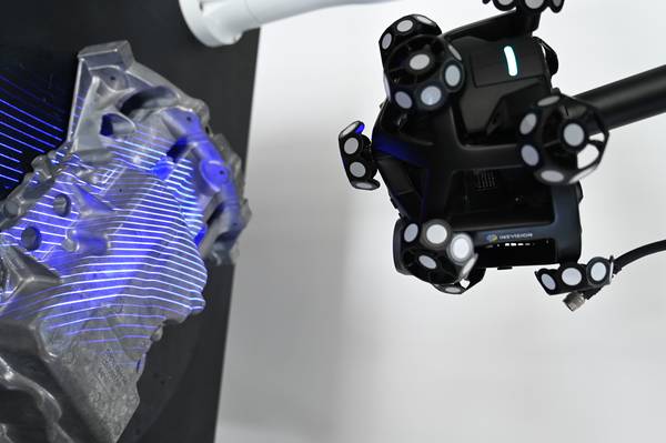
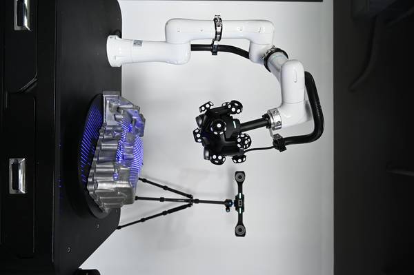
A 3D scanner for large objects projects structured light or laser lines onto a surface and records how those patterns deform across the part. One or more cameras capture the reflected pattern, and triangulation converts the image data into a dense point cloud: millions of XYZ coordinates that describe the surface geometry.
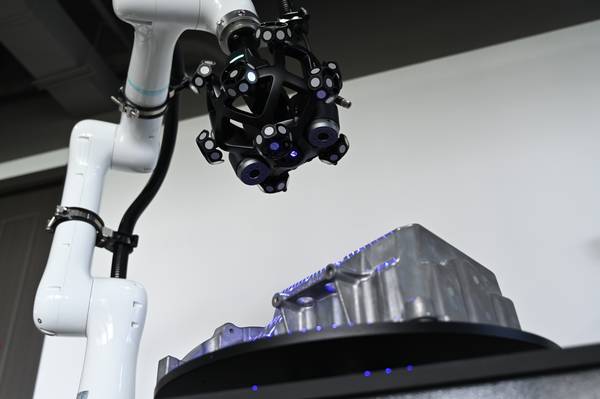
For small components, the scanner may capture most of the part in a few passes. For a large industrial object, that is rarely possible. The system acquires overlapping scan patches from different angles, then software aligns them into one coordinate system. This alignment may rely on physical targets, natural surface features, calibrated reference scales, photogrammetry, or external tracking devices.
The main technical challenge is not only capturing enough points. It is maintaining scale and geometry across the full measurement volume. A scan may look complete on screen while still containing accumulated drift over several meters. For first-article inspection, fit-up verification, or reverse engineering, controlling that drift is what separates useful measurement data from a visually impressive but unreliable model.
How Large-Object 3D Scanning Achieves Measurement Accuracy
The larger the part, the more important global referencing becomes. A small local error in one scan patch can propagate across a 6-meter casting or a 10-meter welded assembly if the software has no stable reference to constrain alignment.
Large-object scanning systems manage this through one or more of the following methods:
- Target-based alignment: adhesive or magnetic targets placed across the surface help the software align overlapping scan areas.
- Feature-based alignment: the software uses recognizable geometric features, such as edges, holes, ribs, or surface transitions.
- Photogrammetric referencing: a camera-based measurement process establishes a global coordinate framework before or during scanning.
- Tracked scanning: an external tracker monitors the scanner’s position as the operator moves around the part.
- Reference scales: calibrated scale bars or reference artifacts help lock the scan to a known physical length.
For a 3d scanner large objects application, these methods are not just workflow preferences. They affect total setup time, operator workload, traceability, and volumetric accuracy. A system that performs well on a 300 mm machined bracket may not maintain the same confidence over an 8-meter frame unless it has a robust strategy for global alignment.
Key Technical Factors That Determine Results
Engineers often compare scanners by looking at a single accuracy value, but large-object inspection requires a broader view. Accuracy, speed, data usability, and environmental robustness all affect whether the system can support production-quality decisions.
| Factor | Why It Matters for Large Objects | What to Evaluate |
|---|---|---|
| Point accuracy | Determines local feature detail, such as holes, edges, and machined faces | Local deviation performance and repeatability |
| Volumetric accuracy | Controls scale across the entire part | Length-dependent accuracy, such as mm/m |
| Setup time | Affects whether scanning fits into production or MRO windows | Target placement, reference setup, calibration steps |
| Alignment method | Controls drift and scan reliability | Targets, tracking, reference scales, or feature alignment |
| Data output | Determines whether results can be used by quality and engineering teams | CAD comparison, mesh export, GD&T reporting |
| Environmental tolerance | Determines whether the scanner works on the shop floor | Ambient light, vibration, temperature variation, surface finish |
Accuracy Is More Than One Number
Point accuracy describes how close an individual measured point is to its true location. This matters for local detail, such as a bolt hole pattern, machined flange, or edge radius.
Volumetric accuracy describes how well the system maintains dimensional consistency across the full measurement space. For large parts, this often dominates the measurement uncertainty budget. A scanner may capture local details within a few hundredths of a millimeter, but if scale drifts by 0.5 mm over several meters, the inspection result may no longer support the tolerance requirement.
For example, if a 10-meter part has a ±0.5 mm profile tolerance, the measurement system must be evaluated against that full length, not just against a small calibration artifact. The question is not simply whether the scanner is accurate. The question is whether the scanner’s volumetric performance fits the part, tolerance, and inspection method.
Speed Includes Setup and Data Processing
Scanning speed is often expressed in points per second, but that number does not describe the full workflow. For large objects, the time spent placing targets, establishing references, walking around the part, checking coverage, and generating inspection reports can exceed the raw capture time.
A practical workflow should be evaluated from arrival at the workpiece to usable output. In heavy manufacturing, aerospace assembly, shipbuilding, and maintenance environments, access windows may be limited. A system that reduces target preparation or automates alignment can make the difference between a scan that supports production and one that disrupts it.
Data Usability Determines Engineering Value
A point cloud is only useful if it can be converted into an engineering deliverable. In inspection, that may mean a deviation color map against nominal CAD, a dimensional report, or GD&T callouts aligned with ISO or ASME practices. In reverse engineering, it may mean a watertight mesh that can be reconstructed into surfaces and imported into CAD.
For a 3d scanner large objects workflow, software compatibility matters. Quality teams may need to move scan data into platforms such as PolyWorks, GOM Inspect, or Geomagic Control X. Engineering teams may need mesh outputs for CAD reconstruction. File handling, alignment records, and repeatable reporting workflows should be part of the technical evaluation.
Shop-Floor Robustness Is Not Optional
Large industrial parts are rarely measured under laboratory conditions. They may sit near welding stations, machining centers, assembly bays, or maintenance areas. Ambient light, temperature gradients, vibration, oil, dust, and mixed surface finishes can all affect measurement.
A suitable system should be evaluated under conditions close to the actual production environment. Laboratory specifications are useful, but shop-floor demonstrations provide better insight into how the scanner behaves around reflective machined surfaces, dark coatings, cast textures, weld seams, and partial line-of-sight constraints.
How 3D Scanning Differs from Adjacent Measurement Methods
Large-object inspection often involves several possible technologies. Each has a valid role, but each also carries workflow constraints.
| Measurement Approach | Typical Large-Part Workflow | Main Constraint |
|---|---|---|
| Fixed CMM | Move the part to the machine or build a dedicated inspection setup | Limited envelope and production disruption |
| Standalone photogrammetry | Place many coded targets, capture image sets, solve global geometry | Preparation time and target density |
| Laser tracker | Measure discrete points or track a probe across the part | Lower surface coverage than dense scanning |
| Gantry-mounted scanning | Use a dedicated cell with rails, foundations, and repeatable motion | Infrastructure cost and limited flexibility |
| Handheld or tracked 3D scanning | Bring the scanner to the part and capture dense surface data on site | Requires access planning and operator skill |
A fixed CMM can deliver very high accuracy on parts that fit within its measurement volume. That same approach becomes difficult when the workpiece is a welded frame, turbine component, mold base, or ship structure. Moving the part can introduce handling risk, downtime, and bottlenecks.
Standalone photogrammetry can establish accurate large-scale geometry, but target placement may take significant time. For some large castings or assemblies, hundreds of coded targets may be required. Tracked scanning and reference-scale workflows can reduce preparation while still constraining global alignment.
Gantry-mounted systems can be effective where part geometry and production flow are stable. They are less flexible when a facility handles mixed-part production, repair work, or large objects that move between bays. Portable scanning is often more practical when the inspection system must follow the workpiece rather than the reverse.
Suitable and Unsuitable Applications
A 3D scanner for large objects is strongest when dense surface data, portability, and flexible setup are more valuable than ultra-high point-by-point probing.
Well-Suited Applications
- First-article inspection of large castings, forgings, weldments, and fabricated structures
- In-process verification during assembly of heavy machinery, aerospace structures, and ship components
- Reverse engineering of legacy parts without reliable CAD data
- Wear, deformation, and repair analysis on molds, press frames, impellers, housings, and gearboxes
- Fit-up and alignment verification during modular construction or large assembly work
- Digital documentation for maintenance, repair, and overhaul operations
Less Suitable Scenarios
- Parts requiring sub-0.01 mm uncertainty across the entire measurement volume
- Deep, narrow internal cavities that cannot be reached by line-of-sight scanning
- Transparent or highly reflective surfaces without surface preparation
- High-speed production checks where every part is identical and cycle time must be extremely short
- Features that require tactile probing due to access, surface, or tolerance constraints
In practice, large-object 3D scanning often works alongside other measurement tools. A scanner may capture the full surface, while a probe, CMM, or tracker verifies critical datum features. The right workflow depends on tolerance, access, inspection frequency, and the type of decision the data must support.
Selection Criteria for Industrial Buyers
Technical buyers should avoid selecting a scanner from a specification sheet alone. A better approach is to map the system against actual parts, tolerances, operators, and reporting requirements.
1. Define the Largest Measurement Volume
Start with the largest part dimension, not the average part size. A system used for a 2-meter housing and a 10-meter welded frame must be evaluated for the larger case. Volumetric accuracy, tracking range, reference setup, and operator movement all change as the measurement envelope grows.
2. Translate Tolerances into Measurement Requirements
Part tolerance should drive scanner selection. If the drawing calls for a profile tolerance across several meters, the scanner’s length-dependent volumetric accuracy must support that requirement. A local accuracy value alone does not confirm that the full part can be inspected with confidence.
3. Evaluate Setup Time Before Scanning Starts
In MRO, shipbuilding, heavy equipment, and aerospace environments, access to the workpiece may be limited. Ask how many targets are required, whether reference scales are needed, how long setup takes, and what happens if the operator must stop and resume scanning later.
4. Confirm Software and Reporting Compatibility
A scanner should fit the existing inspection workflow. If the quality team uses CAD comparison, GD&T reporting, or statistical process documentation, the scan data must move cleanly into those systems. Check file formats, alignment workflows, mesh quality, and report repeatability.
5. Test Under Realistic Conditions
For a reliable selection, manufacturers should validate the scanner with real parts, existing inspection workflows, and reporting requirements before making a decision. INSVISION can support this process with application demos, sample data verification, and practical recommendations for integrating 3D scanning into quality control and production improvement.
Hangzhou Insvision Technology Co.,Ltd.
Address: Building 1, No. 1399 Liangmu Road, Yuhang District, Hangzhou, Zhejiang 311121, China