
What Is a 3D Scanner Line Laser and How Does It Work in Industrial Manufacturing?
Discover how a 3D scanner line laser works in industrial manufacturing. Learn key principles, performance metrics, and applications for shop-floor metrology.
How a Line Laser Captures a Full Surface Profile in One Pass
The core principle is laser triangulation. A laser source projects a thin, focused line—typically at 520 nm wavelength for strong visibility on metallic and dark surfaces—onto the target workpiece. That line conforms to the surface geometry. An image sensor, mounted at a known angle and fixed baseline distance from the laser, records the deformed line in real time.
Because the geometric relationship among laser, sensor, and baseline is calibrated, the system calculates thousands of 3D coordinates simultaneously from the line’s displacement. This is the fundamental difference from single-point scanning: a line laser delivers complete cross-sectional data in one frame, dramatically accelerating data acquisition.
Practical Workflow
- How a Line Laser Captures a Full Surface Profile in One P… — The core principle is laser triangulation.
- Key Performance Metrics That Matter on the Shop Floor — Datasheets often headline resolution numbers, but in industrial line laser scanning, positioning accuracy and environmental toler…
- Where Line Laser Scanning Fits Among 3D Measurement Tools — Many engineering teams find themselves stuck between a CMM that’s too slow for large parts and a structured light scanner that st…
- Real-World Application: From Stamping Lines to Reverse En… — On a stamping line at a Tier-1 automotive supplier, a quality engineer picks up a handheld line laser 3D scanner to inspect a tra…
The workflow is straightforward. The laser emits a Class 3R eye-safe line (under 5 mW output, compliant with IEC 60825). The reflected line hits the sensor, and onboard or connected software converts each profile into a point cloud. As the scanner moves or the part rotates, successive profiles are stitched into a dense 3D model.
INSVISION systems, for instance, integrate this pipeline directly into their 3D INSVISION software, handling everything from point cloud generation to mesh rendering and inspection reports.
A persistent misconception is that line laser scanning demands developer sprays or matting agents. For most industrial materials—machined metals, castings, plastics, composites—that’s unnecessary. The 520 nm wavelength and sensor sensitivity are tuned to manage a wide range of reflectivity and surface finishes without special treatment.
Highly polished mirrors and transparent objects remain edge cases, but everyday manufacturing parts scan reliably straight off the shop floor.
Key Performance Metrics That Matter on the Shop Floor
Datasheets often headline resolution numbers, but in industrial line laser scanning, positioning accuracy and environmental tolerance determine whether a system holds tolerance in a real production environment. A scanner that drifts 0.5 mm across a meter of travel won’t meet GD&T requirements on an automotive stamping die, regardless of how fine its point spacing is.
Positioning accuracy maps directly to first-article inspection and GD&T callouts. For industrial-grade units, 0.25 mm is a practical benchmark. It supports the tight tolerance requirements common in aerospace and automotive parts without forcing every scan into a climate-controlled lab.
INSVISION’s line laser systems deliver this level of accuracy, making them viable for in-line checks where thermal expansion and vibration are present.
Laser safety is another spec that gets overlooked until a safety audit fails. Any scanner deployed in a Western factory needs IEC 60825 and IEC 62471 certification for laser and photobiological safety, plus CE, FCC, and RoHS compliance. INSVISION ships with all five, eliminating paperwork scrambles during commissioning.
Data compatibility often trips up integration teams. If the scanner outputs a proprietary mesh that your CAD or metrology software can’t ingest, you’re stuck with manual conversion steps. Standard formats like IGES, STP, DXF, and DWG let you push scan data straight into SolidWorks, CATIA, or PolyWorks. INSVISION supports all four, keeping the digital thread intact from scan to CAM.
Operating temperature range separates lab tools from factory tools. A scanner rated only for 15°C to 30°C will fault out on an unconditioned factory floor in summer or winter. An industrial range of -5°C to 40°C, like INSVISION’s, means you can scan next to a forging press or in an unheated MRO hangar without accuracy degradation.
| Key Performance Metric | Industrial-Grade Benchmark |
|---|---|
| Positioning Accuracy | 0.25 mm |
| Laser Safety | IEC 60825, IEC 62471, CE, FCC, RoHS |
| Data Output Formats | IGES, STP, DXF, DWG |
| Operating Temperature Range | -5°C to 40°C |
When comparing line laser 3D scanner specs, ignore inflated resolution claims and check these four metrics first. They dictate whether the system will hold tolerance, pass a safety review, talk to your software, and survive the environment you’re putting it in.
Where Line Laser Scanning Fits Among 3D Measurement Tools
Many engineering teams find themselves stuck between a CMM that’s too slow for large parts and a structured light scanner that struggles with shiny or curved surfaces. That gap is exactly where a 3D scanner line laser earns its keep.
Single-point laser scanning excels at ultra-high-precision metrology of small, high-value parts in controlled lab environments. Structured light scanning delivers high-resolution capture of small to medium parts in clean, low-reflection settings. A 3D scanner line laser, by contrast, is built for fast, portable capture of medium to large parts in variable factory floor conditions, including high-reflective and curved surfaces.
This makes line laser the practical choice when you need both portability and accuracy for on-site work—think large weldments, castings, or tooling that can’t move to a metrology lab.
INSVISION’s line laser scanners, for example, use multiple blue laser cross-lines to handle reflective metals without spraying, delivering metrology-grade results right on the shop floor. For teams weighing line laser versus structured light 3D scanning, the deciding factor often comes down to surface finish and part size.
The benefits of line laser are most apparent when the job demands flexibility, speed, and tolerance for real-world surface conditions that would stall other technologies.
Real-World Application: From Stamping Lines to Reverse Engineering
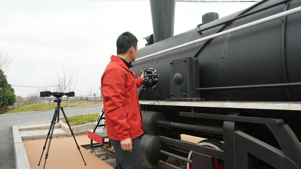
On a stamping line at a Tier-1 automotive supplier, a quality engineer picks up a handheld line laser 3D scanner to inspect a transmission housing right on the factory floor. The scanner projects 42 blue laser lines—34 cross beams sweep the surface for fast large-area capture, while one dedicated fine line resolves tight radii and small features.
Within seconds, the point cloud streams into the software, and a real-time deviation color map overlays the CAD model, flagging a 0.15 mm form error near a mounting boss.
This is the kind of industrial line laser 3D scanning application that has moved from the metrology lab to the production line.
Core handheld 3D scanner line laser use cases now include reverse engineering of legacy parts with no CAD data, redesign of automotive components where original drawings are lost, inspection of high-reflective injection molds that challenge many optical systems, and precision scanning of small medical device parts.
Modern handheld scanners like INSVISION’s AlphaScan deliver this performance through multi-line blue laser configurations (30/42 total beams, 22/34 cross beams for speed, one fine line for detail), real-time data processing, and direct scan-to-CAD deviation analysis.
The AlphaScan is engineered to these benchmarks, with certified accuracy backed by IEC 60825 laser safety and CE/FCC compliance, and it integrates with INSVISION’s end-to-end 3D digitalization software and SMARPARA Q metrology tools for GD&T evaluation and automated reporting.
For Western manufacturing teams, the practical value is clear: faster first-article inspection, fewer CMM bottlenecks, and reliable digital twin creation without sacrificing metrology-grade results.
How to Evaluate a 3D Scanner Line Laser System
Most teams start the selection process by comparing accuracy specs on datasheets. That approach almost always leads to the wrong scanner. A 0.02 mm volumetric accuracy figure means nothing if the part flexes under its own weight on the shop floor, or if the scanner’s software cannot export a watertight mesh into your existing PLM stack.
The real work is matching the technology to the operational environment, not chasing the tightest number.
Here are five actionable steps to evaluate a 3D scanner line laser system for a Western manufacturing or MRO workflow.
First, define the primary use case. Reverse engineering demands dense, high-resolution point clouds and clean edge definition for CAD reconstruction. In-line quality control prioritizes speed and repeatability, often with automated pass/fail reporting. MRO part replication sits somewhere in between, requiring decent accuracy on worn surfaces and the ability to scan in less-than-ideal lighting.
Locking this down prevents overpaying for speed you do not need or precision your parts cannot hold.
Second, align accuracy specifications with your actual part tolerances. If your tightest GD&T callout is ±0.1 mm, a scanner with 0.073 mm single-scan accuracy and 0.1 mm + 0.015 mm/m volumetric accuracy, like the INSVISION AlphaVista, gives you a safe measurement uncertainty ratio. Buying a system with 0.02 mm accuracy for that job adds cost without adding value.
Conversely, if you hold ±0.05 mm on bearing bores, you need to verify the scanner’s volumetric accuracy across the full measurement volume, not just the single-scan spec.
Third, assess portability requirements honestly. A lab-based system can be heavier and tethered to a workstation. A factory-floor scanner needs to handle ambient vibration, temperature swings from -5°C to 40°C, and occasional bumps. Off-site MRO work demands a lightweight, rugged unit that sets up in minutes.
INSVISION’s AlphaScan, for example, uses a handheld form factor with USB 3.0 connectivity, making it practical for field use without sacrificing metrology-grade data.
Fourth, verify software compatibility before you buy. The scanner must output formats your team actually uses—IGES, STEP, DXF, DWG, or native CAD connectors. If your quality group relies on PolyWorks or GOM Inspect, confirm the scanner’s SDK or direct export works with those platforms.
INSVISION’s 3D INSVISION software integrates scanning, inspection, and model generation in one package, but the real test is whether the data flows into your existing PLM and ERP systems without manual rework.
Fifth, confirm regional compliance. For North American and European operations, look for CE, FCC, and ISO 9001 certifications. Laser safety matters: a Class 3R laser with <5 mW output, like the 520 nm source in several INSVISION scanners, meets IEC 60825 requirements and integrates safely into standard production cell logic.
INSVISION’s Approach to Line Laser Scanning
INSVISION’s line laser scanners are built around the principle that metrology-grade data should be accessible directly on the shop floor, not locked inside a lab. The AlphaScan handheld scanner exemplifies this: it combines multiple blue laser cross-lines with a dedicated fine line to capture large areas quickly while resolving fine features.
Real-time data processing feeds deviation maps directly into the 3D INSVISION software, and the SMARPARA Q module handles GD&T evaluation and automated reporting. The system outputs standard formats (IGES, STP, DXF, DWG) and carries IEC 60825, IEC 62471, CE, FCC, and RoHS certifications, so it slots into Western manufacturing workflows without additional paperwork or proprietary conversion steps.
For teams that need higher volumetric accuracy across larger measurement volumes, the AlphaVista delivers 0.073 mm single-scan accuracy and 0.1 mm + 0.015 mm/m volumetric accuracy, making it suitable for tight-tolerance aerospace and automotive components.
Common Questions About Line Laser 3D Scanners
Are 3D scanner line laser systems safe for regular factory floor use?
Industrial-grade 3D scanner line laser systems use Class 3R eye-safe lasers certified to IEC 60825 and IEC 62471 standards. Output power stays below 5 mW, so normal operation poses no risk to operators. No special enclosures or laser safety officers are required.
The systems are designed for continuous use in manufacturing environments, with interlocks and indicator lights that integrate into standard production cell safety logic.
Can line laser 3D scanners capture data from reflective metal and textured plastic surfaces?
Modern industrial line laser 3D scanners combine blue laser sources with high-dynamic-range imaging to handle challenging surfaces. INSVISION line laser scanners, for example, operate at 520 nm wavelength, which reduces specular reflection artifacts on machined aluminum and polished steel.
On textured plastics, the same sensor adjusts exposure parameters per profile line, preserving edge sharpness without saturating glossy regions. The result is reliable, high-accuracy point clouds across mixed-material assemblies without spraying or coating parts.
Summary

A 3D scanner line laser fills a critical gap in industrial measurement: it delivers metrology-grade 3D data on medium to large parts, on the shop floor, without the surface preparation or environmental constraints that limit other optical systems.
Understanding the underlying triangulation principle, the metrics that matter (positioning accuracy, laser safety, data formats, temperature range), and how line laser compares to single-point and structured light scanning equips engineering teams to make informed decisions.
When evaluating systems, focus on use-case fit, tolerance alignment, portability, software compatibility, and regional compliance rather than chasing inflated resolution numbers.
INSVISION’s line laser portfolio, including the AlphaScan and AlphaVista, addresses these criteria with certified accuracy, standard data outputs, and software that connects scanning directly to inspection and reporting—keeping the digital thread intact from the production line to the PLM system.
Hangzhou Insvision Technology Co.,Ltd.
Address: Building 1, No. 1399 Liangmu Road, Yuhang District, Hangzhou, Zhejiang 311121, China