

What a 3D Scanner for Reverse Engineering Changes on the Shop Floor
3d scanner for reverse engineering: A quality engineer receives a legacy pump housing that needs replacement tooling, rework, or a new CAD model.
Why Point-Based Measurement Leaves Gaps
A CMM is often treated as the default choice for any geometric task. That assumption works for discrete prismatic features, but it breaks down on freeform surfaces, blended radii, and undercut areas where a touch probe cannot collect enough points to define the actual surface. The limiting factor is rarely probe accuracy. It is point density and geometry access.
Scenario Snapshot
A practical way to read the article is through this scenario:
- Why Point-Based Measurement Leaves Gaps: A CMM is often treated as the default choice for any geometric task.
- What a 3D Scanner for Reverse Engineering Actually…: The core idea is surface capture.
- The Shop-Floor Workflow That Makes Scanning Usable: A 3D scanner for reverse engineering only improves the process when scan, compare, review, and report stay connect…
Hard gauges create a related blind spot. A gauge tells you whether a diameter or position is within tolerance. It does not provide the continuous surface data needed to reconstruct an unknown part, trace a parting line, or repair a worn contour. CMM programming also adds time for one-off reverse engineering work.
A 3D scanner for reverse engineering changes the capture rhythm by acquiring full surface sections near the machine, reducing the need to move the part to a lab or return to it repeatedly for missed geometry.
What a 3D Scanner for Reverse Engineering Actually Does
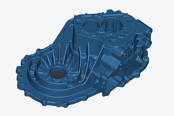
The core idea is surface capture. Instead of recording a limited set of points, an optical handheld scanner collects dense surface data as a point cloud. Software aligns multiple captures into a mesh that represents the as-built part. From there, the file can move into CAD for modeling or into inspection software for comparison against a reference.
This approach matters most when the part is not defined by a small number of simple features. Surfaces with curvature, blend transitions, or irregular wear are difficult to describe with calipers and radius gauges. A dense mesh gives the engineer a continuous reference for building a new parametric model or checking how the current part deviates from an existing master.
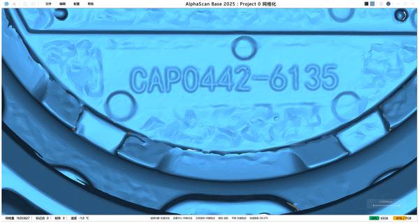
The value is not simply having more points. It is being able to reconstruct the feature relationships that discrete measurement methods miss. That capability depends on how well the scanner handles edges, holes, and sharp transitions, not just how many points it collects.
The Shop-Floor Workflow That Makes Scanning Usable
A 3D scanner for reverse engineering only improves the process when scan, compare, review, and report stay connected.
- Capture as-built surfaces from the part, tool, or repair area.
- Compare the mesh or point cloud against the reference CAD or a previously scanned master.
- Review defined callouts rather than relying on color maps alone: surface profile, wall thickness, hole position, trim edge, and GD&T zones.
- Report annotated deviation views and pass/fail tables tied to the inspection criteria.
The risk is not usually the scanning itself. The risk is manual editing between capture and report. If the mesh requires heavy cleanup before it enters CAD or inspection software, the scanner becomes a bottleneck. For this reason, quality teams should validate file compatibility and tolerance banding before accepting any scanning system.
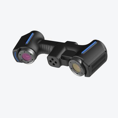
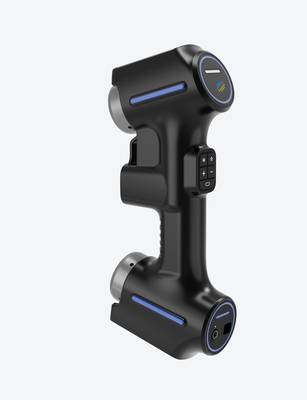
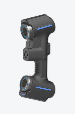
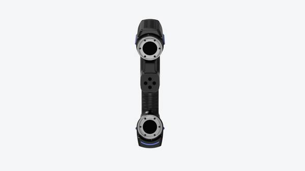
INSVISION AlphaScan supports this loop as a handheld dense-surface capture tool. Its practical fit depends on whether the scanned data moves cleanly into the comparison and reporting software the team already uses.
Where the Process Fits and Where It Needs Control
Handheld scanning fits well when a part can be brought to a stable, well-lit area and does not have deep hidden cavities or highly polished surfaces without preparation.
| Validation area | What to confirm |
|---|---|
| Surface readiness | Dark, transparent, or mirror-like areas may need temporary matting or developer spray. |
| Alignment strategy | Parts with few distinct features may require temporary reference targets to keep scans registered. |
| Output requirements | A watertight mesh, a STEP file, or GD&T-driven CAD features will change scan density and post-processing. |
| Environmental stability | Nearby vibration, moving equipment, and strong ambient light can affect handheld scan quality. |
These are not scanner limitations alone. They are boundary conditions for any optical measurement method. When they are controlled, the resulting data is more likely to be usable without extensive rework.
Selection Criteria That Matter on Actual Geometry
A spec sheet is a starting point, not a validation result. For reverse engineering, the more practical evidence comes from testing the scanner on a workpiece that includes known holes, edges, and blended surfaces.
- Can the scan data hold edge definition well enough for CAD reconstruction?
- Do hole positions and trim edges remain stable after mesh export?
- Can the file move into existing CAD or inspection software without manual repair?
- Does the scan show enough surface profile detail for the intended repair or modeling task?
If a part requires a watertight mesh for 3D printing or simulation, that requirement should be identified before scanning. If the team needs a parametric CAD model, the downstream modeling approach will influence scan density and alignment. Clarifying these deliverables early prevents the scanner from being evaluated against the wrong task.
Where INSVISION AlphaScan Fits
The INSVISION AlphaScan handheld 3D scanner is positioned for dense surface capture near the machine, not as a replacement for every metrology tool in the shop. It fits reverse engineering workflows where the part is accessible, surface preparation is controlled, and the output deliverable is defined.
Its role is to close the data gap that point-based measurement leaves on freeform and blended geometry. When engineering teams need continuous as-built surfaces for CAD reconstruction or deviation analysis, a handheld scanner can reduce the number of return visits to the part.
The system still requires the same discipline as any measurement process: alignment strategy, surface preparation, and validation against known reference features.
Common Questions
Does a 3D scanner for reverse engineering replace a CMM?
No. It changes where each tool is used. A CMM still works well for discrete feature verification and tight GD&T callouts on accessible geometry. Scanning covers dense surface capture, freeform shapes, and areas where point density determines whether the model can be rebuilt.
When should I avoid handheld scanning?
Avoid it when the part has deep hidden cavities that optical capture cannot reach, when the surface is highly polished and cannot be prepared, or when the scan environment has strong vibration and moving equipment. Parts with very few distinct features may also require added targets for reliable alignment.
Do I need spray for every part?
No. Dark, transparent, and mirror-like surfaces often need temporary matting or developer spray. Some materials scan without preparation, but the best approach is to validate surface response on the actual part before committing to a full inspection routine.
What deliverable should I specify before scanning?
Define whether you need a watertight mesh, a STEP file, or a GD&T-driven CAD model. The required output changes scanning density, alignment, and post-processing. If multiple outputs are needed, plan for them before capture rather than after the mesh is built.
How do I know the scanner will hold edge and hole position on my part?
Use an acceptance test on known geometry. Scan a reference section with holes and defined edges, compare the result against independent measurements, and inspect the exported mesh or CAD file for distortion. A scanner can be considered suitable only after this type of on-part validation.
Summary
A 3D scanner for reverse engineering solves a specific shop-floor problem: capturing continuous surface data when traditional measurement tools miss freeform geometry and blended transitions. It is not a universal replacement for CMM or hard gauges. The decision should be based on the workpiece, the downstream CAD or inspection deliverable, and the environment in which the scanner will operate.
The workflow matters as much as the hardware. Surface preparation, alignment strategy, file export, and report generation determine whether the scan data becomes useful or creates new rework. INSVISION AlphaScan fits that workflow when teams validate the process on actual part geometry and use the scanner where dense surface capture adds real value.
Hangzhou Insvision Technology Co., Ltd.
Address: Building 1, No. 1399 Liangmu Road, Yuhang District, Hangzhou, Zhejiang 311121, China
Copyright © Hangzhou Insvision Technology Co., Ltd. All rights reserved.
Copyright © Hangzhou Insvision Technology Co., Ltd. All rights reserved.