

Industrial 3D Scanner Tool Workflow From Dense Surface Capture to Audit-Ready Inspection Reports
3d scanner tool: In aerospace, automotive, energy, and medical device manufacturing, the gap between production and inspection often creates more cost than.
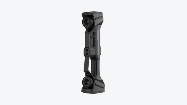
This article explains the full 3D scanner tool workflow for large-format industrial parts: what the technology does, how scan planning and processing affect results, where it fits, and where validation is still required.
What a 3D Scanner Tool Is and How It Works
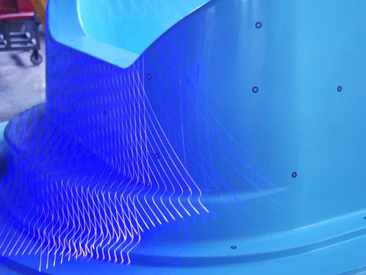
A 3D scanner tool is a non-contact optical measurement device. It projects light onto a surface, reads the return signal, and builds dense point cloud geometry without touching the component. Unlike a touch probe that samples individual coordinates, an industrial scanner captures thousands of points per pass across contours, flanges, bores, and edges.
Key Points at a Glance
- A 3D scanner tool is a non-contact optical measurement device.
- Before a 3D scanner tool is brought to the part, production and quality teams should agree on what stable scan data looks like.
- Large assemblies are often expensive to move or difficult to fixture repeatedly.
- Raw geometry from a 3D scanner tool is only the starting point.
That density creates three practical advantages. First, surface profile analysis can cover more of the part than a sparse point set allows. Second, GD&T feature extraction uses the same data source for multiple characteristics. Third, the captured geometry can be reused for reverse engineering or digital archive purposes without a separate measurement campaign.
The processing pipeline, not the hardware alone, controls repeatability. A raw point cloud becomes useful only after alignment, filtering, mesh generation, and CAD comparison are standardized.
Pre-Scan Preparation Determines Data Quality
Before a 3D scanner tool is brought to the part, production and quality teams should agree on what stable scan data looks like. A rushed shop-floor setup may produce clean surfaces but poor feature alignment, which creates rework later.
For large composite assemblies, production technicians need rigid, repeatable fixturing. Reflective or textured surfaces may require a matte developer or target dots, applied only where surface finish is not a measured characteristic. Quality engineers should identify which GD&T features drive acceptance and place reference points at those locations before scanning begins.
Bores, flanges, and thin edges then receive enough point density for ISO/ASME evaluation without scanning the entire part at maximum resolution.
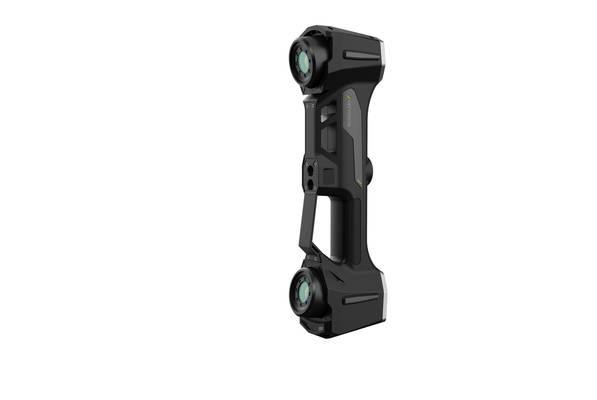
The INSVISION AlphaVista large-format handheld 3D scanner tool fits production line work because it captures dense data quickly on large surfaces. The greater benefit comes from a shared scan plan that limits part handling and reduces variation that post-processing cannot fully correct.
Handheld Capture and Scan Path Planning for Large Parts
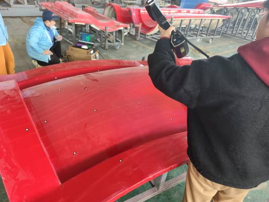
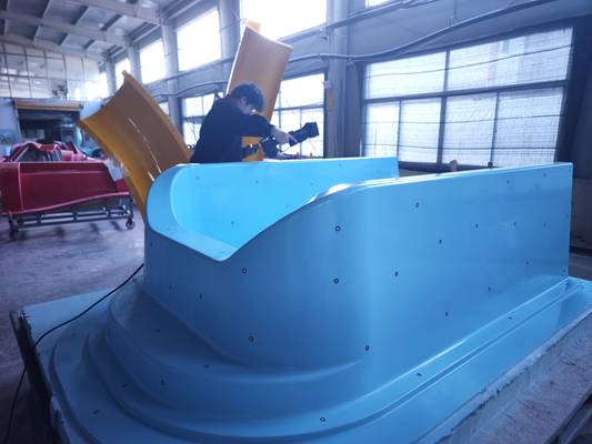
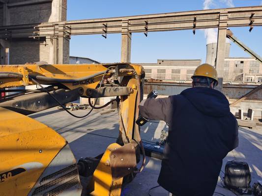
Large assemblies are often expensive to move or difficult to fixture repeatedly. A handheld 3D scanner tool addresses that by operating at the station. The scanner itself projects light, reads the return signal, and builds point cloud geometry without contact. Scan path planning then becomes the main quality control.
Operators should use systematic overlapping passes so that recesses, flanges, and brackets do not create shadow gaps. Consistent standoff distance keeps point spacing uniform. After each pass, alignment features or reference targets should be checked to confirm that multi-scan stitching remains within tolerance.
This in-situ approach removes the need for a fixed metrology station and reduces part repositioning. INSVISION AlphaVista is designed for large-format capture, allowing production technicians and quality inspectors to run scans at the station and hand point cloud data to exception review without changing production flow.
Point Cloud Processing Pipeline
Raw geometry from a 3D scanner tool is only the starting point. A standardized processing template is what reduces operator variability and speeds up inspection turnaround.
The typical handoff starts with automatic alignment of raw scan passes into a single reference frame. Noise filtering removes loose artifacts. Mesh generation creates a usable surface model that is aligned to nominal CAD for deviation comparison. Quality engineering then drives dimensional extraction: GD&T callouts, surface profile bands, and edge positions.
Common deliverables include:
| Deliverable | Description | Typical Use |
|---|---|---|
| Raw point cloud | Unfiltered, high-density data | Advanced engineering analysis and root cause investigation |
| Deviation heatmap | Color-mapped CAD comparison | Quick pass/fail checks and shop-floor review |
| GD&T report | Extracted dimensions and datum references | Quality sign-off and first-article inspection |
| Reverse-engineered CAD | Modeled surfaces and edge geometry | Tooling adjustments and modified part reproduction |
| Mesh file | Watertight polygon model | FEA, digital archive, or machining preparation |
Reporting and Reinspection Protocols
Model-based definition and closed-loop quality data have changed what an inspection report needs to carry. Aerospace, automotive, and energy teams increasingly expect more than a pass/fail PDF. A useful report combines annotated deviation heatmaps, feature-by-feature dimension tables, and traceable data logs aligned with ISO and ASME expectations.
Reinspection triggers should also be defined across teams. Typical rules include deviations outside tolerance thresholds, batch-to-batch variation that signals process drift, and tooling wear indicators on forming or cutting tools. Documenting those triggers keeps production, quality, and tooling teams working from the same evidence base.
For lean manufacturing to work without wasted inspection loops, the 3D scanner tool should export standard mesh, point cloud, and inspection data formats that QMS and PLM systems can accept without manual rework. INSVISION AlphaVista supports those standard formats, so scan results remain accessible across the product lifecycle instead of sitting in a metrology silo.
Where a 3D Scanner Tool Fits and Where It Does Not
A 3D scanner tool is not a one-to-one CMM replacement in every situation. The table below compares the two workflows at a category level.
| Criteria | Contact CMM | Industrial 3D Scanner Tool |
|---|---|---|
| Coverage | Sparse point set | Dense surface point cloud |
| Setup | Fixed metrology station, part handling | In-situ, portable |
| Output | Coordinate data, dimensional reports | Point cloud, mesh, deviation heatmap, reverse CAD |
| Validation | Long-established reference | Requires correlation to CMM or calibrated artifact |
The technology is well suited to large-format parts such as airframe skins, composite layup tools, and energy housings. It also supports in-process checks where moving the part to a metrology lab would disrupt production.
The main limitations are optical, not computational. Deep narrow bores or surfaces that cannot be reached by projected light may require contact probing or separate sensors. Reflective or highly absorptive surfaces can reduce data quality without proper preparation. In all cases, a new scanning process should be correlated against a CMM or calibrated reference artifact before it replaces existing inspection steps.
Selection Considerations for a 3D Scanner Tool
When evaluating a 3D scanner tool, accuracy specifications are only one input. Teams should also consider scan volume, standoff distance, edge resolution on GD&T features, available data formats, operator training, and correlation requirements.
A practical evaluation sequence can include:
- Define the part families and GD&T features that create inspection bottlenecks.
- Run a correlation study on representative parts against a CMM or calibrated artifact.
- Write station-level instructions for calibration, scanning, file handoff, and exception escalation.
- Standardize file naming with part number, revision, station, and operator traceability.
- Confirm that exported point cloud, mesh, and inspection data move into QMS or PLM systems without manual rework.
Hardware capability does not replace process validation. The most important selection criterion is whether the surrounding workflow can turn dense scan data into faster, traceable decisions.
INSVISION AlphaVista in the Capture-to-Report Sequence
For large assemblies that are costly to move or difficult to fixture repeatedly, a large-format handheld scanner reduces setup and part handling. INSVISION AlphaVista is built for this capture-to-report workflow: it captures dense data across larger surfaces while preserving local detail for GD&T evaluation and reverse engineering deliverables.
The product’s role in a quality system depends on more than scanning speed. Its standard mesh, point cloud, and inspection data output supports the handoff to QMS and PLM environments. That makes the 3D scanner tool a measurement input into a broader quality loop rather than a disconnected metrology device.
Its practical value on the shop floor depends on pre-scan planning, standardized processing templates, and clear exception review rules.
Common Misconceptions and Technical Q&A
Q: Can handheld 3D scanner tools deliver data accurate enough for aerospace or medical device inspection?
A: Industrial handheld scanners are designed to support stringent tolerance requirements, but that does not remove the need for validation. Before using an INSVISION AlphaVista for first-article inspection or in-process checks, a quality team should correlate scan results against a CMM or calibrated reference artifact on the actual part geometry, surface finish, and GD&T callouts involved.
Thermal soak, part fixturing, reference targets, and scan volume all affect reported deviation. The right workflow treats the scanner as one measurement input, not a standalone pass/fail authority.
Q: Do 3D scanner tools require specialized operators on the shop floor?
A: Modern handheld models are designed for intuitive operation. Production technicians can handle routine scanning after targeted training on the specific part family and station setup. The quality engineer still owns alignment, tolerance zones, report templates, and exception review.
A practical handoff has the technician verify the calibration artifact, confirm part orientation, scan the defined regions, and upload the raw scan file. The quality team then reviews the color map, runout, profile, or flush condition against the control plan. That split keeps data collection on the floor while pass/fail decisions remain with quality.
Q: Can scan data integrate with existing Industry 4.0 and lean manufacturing initiatives?
A: Yes. Standard deliverables such as point clouds, mesh data, and deviation reports can be routed into QMS, PLM, and process analytics tools. The key is not the file format alone. It is agreeing on a deterministic traceability standard—part number, revision, station, and operator—before scanning begins.
When the scan output carries that traceability, it can support digital twin updates, trend charts, and root cause analysis of form or assembly issues. Without that handshake, even high-quality scanner data becomes another disconnected file.
Summary
A 3D scanner tool is not a lab-only instrument and not a standalone authority in an industrial quality system. On large-format parts, its value comes from a defined station workflow, a standardized processing pipeline, and a clear exception review process.
Teams evaluating INSVISION AlphaVista should start with a correlation study on representative parts, define who scans and who accepts, and standardize the data deliverable with full traceability. When those pieces are in place, the scanner changes inspection from sparse point checks to dense surface evidence that production and quality can act on before rework moves downstream.
Hangzhou Insvision Technology Co., Ltd.
Address: Building 1, No. 1399 Liangmu Road, Yuhang District, Hangzhou, Zhejiang 311121, China
Copyright © Hangzhou Insvision Technology Co., Ltd. All rights reserved.
Copyright © Hangzhou Insvision Technology Co., Ltd. All rights reserved.