

What Engineers Need to Know About 3D Scanner Accuracy on the Factory Floor
Those lab measurements were collected on a granite table in a temperature-controlled room, using a matte, calibrated artifact.
Why Stated 3D Scanner Accuracy Rarely Translates Directly to Factory Performance
When a 3D scanner arrives on a factory floor, the datasheet number that impressed the procurement team—often a single-digit micron value—immediately collides with shop air hammers, overhead lighting, and parts with mill scale or oil residue. Those lab measurements were collected on a granite table in a temperature-controlled room, using a matte, calibrated artifact.
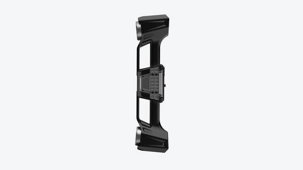
None of that replicates the reality of an automotive body-in-white line, an aerospace MRO cell with a turbine blade still in its fixture, or a medical device assembly area where the part surface finish wanders from batch to batch. The result is a gap that can delay rollout, force rework of inspection programs, and trigger a failed GR&R or AS9100 audit.
Scenario Snapshot
A practical way to read the article is through this scenario:
- Why Stated 3D Scanner Accuracy Rarely Translates Di…: When a 3D scanner arrives on a factory floor, the datasheet number that impressed the procurement team—often a sin…
- Sample Validation: Confirming 3D Scanner Accuracy f…: Committing to a 3D scanning system without testing it on your own production parts is a risk most quality managers…
- Workflow Integration: Maintaining Consistent 3D Sca…: A 3D scanner that passes a first-article inspection on day one can still produce drifting results on day thirty if…
Closing that gap is not a matter of shopping for a tighter specification. It requires a structured validation sequence that starts with the real-world parts and the existing quality system. A CMM-correlated golden part, measured under the same environmental conditions the scanner will see, reveals how the scanner’s dynamic accuracy behaves when the floor trembles and the light flickers.
Deployment Validation Checklist
| Focus Area | Decision Point | Deployment Note |
|---|---|---|
| Target part | Check size, surface condition, and key tolerances against the scan task | Run a full trial scan on a representative part |
| Data workflow | Verify point cloud, deviation map, and quality-report handoff | Confirm export formats and review ownership in advance |
| Shop-floor use | Review training, calibration, lighting, and working space | Keep the validation record as a repeatable inspection reference |
Sample Validation: Confirming 3D Scanner Accuracy for Your Exact Parts and Conditions
Committing to a 3D scanning system without testing it on your own production parts is a risk most quality managers won’t take. A structured sample validation workflow eliminates that uncertainty before the equipment ever reaches the shop floor.
It starts with part selection: pull a few representative components that include the gnarly features your regular inspection reports flag—deep pockets, near-zero draft angles, cast surfaces with varied roughness, and anything large enough to push the scanner’s working volume. Don’t pick the easy prismatic block that measures well on everything.
The accuracy metrics you prioritize depend on what you actually need from the scan data. If you’re feeding GD&T callouts into a CMM software alignment, volumetric length accuracy and sphere spacing error matter more than mesh noise. For surface profile verification against CAD, look at the scanner’s ability to resolve fine edges and thin walls without smoothing them out.
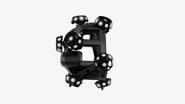
Replicating your on-site conditions during the test is just as critical. Temperature swings, ambient vibration from nearby presses, and shop floor lighting all influence how a tracking-based system like INSVISION’s V-Track holds its calibration.
Workflow Integration: Maintaining Consistent 3D Scanner Accuracy Across Daily Operations
A 3D scanner that passes a first-article inspection on day one can still produce drifting results on day thirty if the integration plan ignores the realities of the production floor. Initial accuracy specs matter, but long-term measurement consistency is shaped by how the equipment gets embedded into daily routines. Calibration cycles aligned with ISO 9001 or AS9100 requirements keep the baseline stable.
More importantly, the path from scan data to actionable report needs to plug directly into existing CAD and CMM quality pipelines without forcing engineers to rework their entire comparison workflow.
Different environments call for different approaches. High-volume assembly lines benefit from automated, repeatable sequences where the scanner becomes a fixed station within the line. Low-volume MRO bays, on the other hand, need flexible setups that can adapt to mixed part geometries and unpredictable inspection cadences. INSVISION’s V-Track tracking system addresses the latter scenario particularly well.
Because it relies on continuous position tracking rather than repeated part alignment, large-part and multi-station inspections maintain accuracy across the entire scan volume. You scan, the system tracks, and the point cloud stays referenced to the same coordinate frame throughout.
From there, the measured data flows into a comparison module against the nominal CAD model, deviations get reviewed against GD&T callouts, and a report is generated that quality teams trust. The process moves from scanning to comparison to review to reporting without disruption, preserving accuracy and fitting naturally into lean manufacturing and Industry 4.0 quality loops.
Data Reporting and Traceability: Linking 3D Scanner Accuracy to Compliance Requirements
A wave of recent OEM audits has made one thing clear: a measurement result without a chain of custody is no longer acceptable. When a supplier submits a dimensional report under IATF 16949, AS9100, or ISO 13485, auditors now expect to trace that result back through the sensor’s calibration status, the environmental conditions at the time of acquisition, the software algorithm version, and the operator who performed the scan.
If that trail breaks, the report gets rejected—even if the part itself was good.
INSVISION’s V-Track system addresses this by embedding accuracy metadata directly into the measurement output. As the scanner captures geometry, the software automatically logs volumetric accuracy, probing error, and sphere spacing error from the sensor’s live calibration data. It timestamps every scan, locks the GD&T evaluation to the aligned reference system, and appends the hardware serial number and firmware revision.
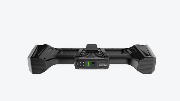
The result is a single digital record that maps each reported dimension to the specific accuracy conditions under which it was measured.
This data can be structured to match standard industry report formats—AS9102 First Article Inspection templates, PPAP dimensional results, or medical device design history file entries—without manual rekeying.
The metadata flows into existing QMS platforms like SAP QM, IQS, or ETQ Reliance through direct exports, so the quality team sees the scan data inside the same dashboard they already use for nonconformance tracking and corrective actions. The scanner becomes a native data source in the plant’s quality ecosystem, not a standalone tool that forces someone to transcribe numbers by hand.
For a plant moving toward a paperless audit trail, the deliverable isn’t just the point cloud or the CAD
Training and Periodic Review: Sustaining 3D Scanner Accuracy for Long-Term Use
Sustaining 3D scanner accuracy over years of shop floor use relies on role-specific training and structured periodic checks, not just initial calibration. Quality engineers learn GD&T alignment and calibration drift troubleshooting to catch discrepancies early. Line technicians master part fixturing, scan parameter adjustments, and daily pre-run reference checks for consistent routine operation.
Procurement teams gain context for how compatible consumables preserve measurement integrity, avoiding off-spec components that skew results.
Periodic reviews compare current performance against initial sample validation benchmarks from commissioning. Full re-validation is required for new part families, facility relocations, or production environment shifts outside the system’s rated operating range, such as sustained temperature fluctuations.
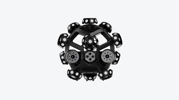
INSVISION provides targeted, role-based training for V-Track users and optional periodic accuracy review services aligned with lean manufacturing continuous improvement, keeping the system a reliable long-term quality workflow asset. This approach works best for high-tolerance production lines; on-site teams should verify review cycles match existing audit cadences and staff have current competency documentation.
Hangzhou Insvision Technology Co., Ltd.
Address: Building 1, No. 1399 Liangmu Road, Yuhang District, Hangzhou, Zhejiang 311121, China
Copyright © Hangzhou Insvision Technology Co., Ltd. All rights reserved.
Copyright © Hangzhou Insvision Technology Co., Ltd. All rights reserved.