

A Constraint-First Approach to 3D Scanning Parts for Large Assemblies
When quality teams inspect heavy equipment subassemblies on the shop floor, standard 3D scanning parts workflows often fail.
Quality engineers in heavy equipment manufacturing know the
Quality engineers in heavy equipment manufacturing know the routine: a welded frame or large casting sits on a production fixture, and the portable CMM arm can’t reach the back side of a critical datum. Three shifts of repositioning later, the inspection report still has a void where the weld toe distortion values should be. Moving the part to a metrology lab isn’t an option.
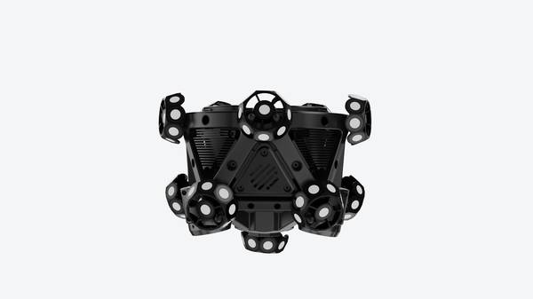
It’s too large, too tightly fixtured, and the line is already running at takt. That’s the moment when a handheld 3D scanner becomes appealing—and a moment when a generic scan-and-stitch workflow can waste more time than it saves.
Key Points at a Glance
- Quality engineers in heavy equipment manufacturing know the routine: a welded frame or large casting sits on a production fixture, and the porta…
- Most first-time handheld scanning users discover the hard way that the shop floor is not a metrology lab.
- Site conditions.
- When an inspection workflow moves from a temperature-stable lab to the shop floor, the same routine that produces clean data in a controlled roo…
Capturing usable dimensional data from non-portable assemblies is not a matter of better hardware alone. It’s a diagnostic exercise. Geometry, material, site conditions, and production timeline each impose constraints that, if ignored, break the data continuity that downstream inspection and reverse engineering tasks depend on.
Deployment Validation Checklist
| Focus Area | Decision Point | Deployment Note |
|---|---|---|
| Target part | Check size, surface condition, and key tolerances against the scan task | Run a full trial scan on a representative part |
| Data workflow | Verify point cloud, deviation map, and quality-report handoff | Confirm export formats and review ownership in advance |
| Shop-floor use | Review training, calibration, lighting, and working space | Keep the validation record as a repeatable inspection reference |
This article walks through a constraint-first approach to 3D scanning parts for large industrial assemblies, built for manufacturing technologists, quality managers, and procurement teams evaluating on-floor measurement solutions.
Most first time handheld scanning users discover the
Most first-time handheld scanning users discover the hard way that the shop floor is not a metrology lab. The constraints don’t announce themselves until a scan fails halfway through a feature. They fall into four categories.
Part geometry. Deep cavities in a cast transmission housing, weld seams along a heavy equipment frame, and overhanging structural members trap the scanner’s line of sight. Without careful projection angles, these areas return no data or produce stitching errors that cascade into the rest of the model. The tightest GD&T callouts often live right where access is worst.
Material properties. Reflective carbon steel, matte composite overlays, and thick powder-coated surfaces respond differently to structured light. A surface that looks easy to scan with the naked eye can create blinding reflections or absorb enough light to kill the signal-to-noise ratio. A single assembly might mix all three surface types, forcing an operator to adjust scan parameters repeatedly.
Site conditions
Site conditions. Uncontrolled lighting, stray reflections from overhead cranes, and limited access around fully assembled units rule out a textbook tripod setup. Dust, vibration, and ambient temperature swings shift the scan reference frame. There is no climate-controlled measurement bay. The scan has to work where the part sits.
Timeline. In many production environments, takt times are measured in minutes. An off-site lab measurement is non-negotiable. Scanning must happen in-line, without disrupting the build sequence. The workflow must be fast enough to support first-article verification, in-process weld distortion checks, or reverse engineering of legacy parts for MRO spares, all without pulling the asset from the fixture.
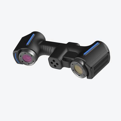
A scan strategy that ignores any one of these four factors—geometry, material, site, or timeline—will break the data continuity. The result is a mesh that looks complete on screen but drifts out of tolerance at the features that matter most.
How Uncontrolled Shop Floors Break Scan Data
When an inspection workflow moves from a temperature-stable lab to the shop floor, the same routine that produces clean data in a controlled room often breaks. Three failure modes appear repeatedly.
Alignment drift across large scan volumes. Without a measurement strategy that locks global reference features early, each successive scan pass accumulates small angular and translational errors. On a casting or welded assembly longer than a meter, that drift can push the final point cloud outside the tolerance band needed for a first-article inspection report.
The coordinate system wanders, and the deviation map becomes unreliable.
Hidden features that never get captured
Hidden features that never get captured. Deep counterbores, narrow blade-to-shroud clearances on impellers, and the back side of mounting flanges remain invisible when the scan path is planned only for visible surfaces. If the scanner head cannot reach the feature, or if the operator must stay outside a safety zone, the resulting mesh has voids exactly where the dimensional controls are tightest.
That incomplete data turns a full-field inspection into a gamble.
Surface noise that masks actual defects. Direct sunlight through a bay door, overhead LED glare, or a polished stainless-steel surface can throw thousands of spurious points into the scan. On a matte-coated part, the same scanner might produce a clean point cloud, but the contrast forces the operator to recalibrate between passes.
If the noise is filtered too aggressively, actual anomalies like casting flash or weld spatter can be erased along with the reflections.
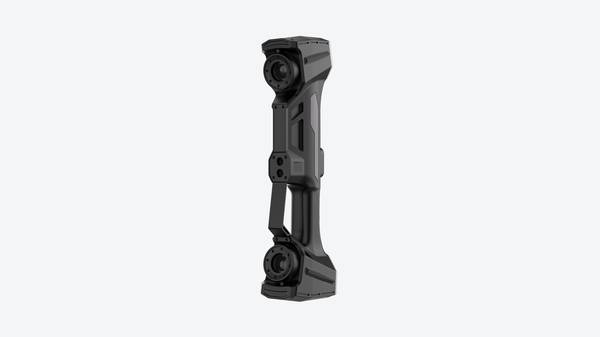
These failures share a root cause: the scanning workflow was not designed around the constraints of the specific part and its environment.
Hangzhou Insvision Technology Co., Ltd.
Address: Building 1, No. 1399 Liangmu Road, Yuhang District, Hangzhou, Zhejiang 311121, China
Copyright © Hangzhou Insvision Technology Co., Ltd. All rights reserved.
Copyright © Hangzhou Insvision Technology Co., Ltd. All rights reserved.