

Why a Single 3D Scanner Accuracy Number Misleads Large Part Inspection Teams
That workflow gets amplified by vendor marketing that boils everything down to one headline figure. Pre-arranged vendor demos with pristine artifacts prove nothing.
The Myth of Single-Spec 3D Scanner Performance for Large Parts
On a typical automotive body-in-white program, a quality team will pull three or four spec sheets, line up the stated volumetric accuracy numbers, and shortlist the 3D scanner with the smallest single value. That workflow gets amplified by vendor marketing that boils everything down to one headline figure.
The problem is that a single-point accuracy spec, measured under a lab’s narrow thermal window and short standoff, tells you almost nothing about how the system will behave on a 12-meter wind blade root, a large composite MRO panel, or a full car body fixture.
Real-world large part dimensional inspection introduces boundary conditions that scatter performance fast: temperature drift across the scan volume, part movement between passes, reference scale error accumulation, and the need to hold GD&T compliance across datums spaced meters apart.
A quality lead who focuses only on that one spec line often ends up with a tool that passes a benchtop validation but fails correlation on the floor—wrong tooling, unresolved surface profile callouts, and a scanning setup that cannot deliver repeatable, reviewable outputs.
Any industrial 3D scanning evaluation for large-scale work has to start with how the system manages those boundary conditions, not with a cherry-picked single-spec headline.
INSVISION’s approach with the AlphaVista platform, for example, builds the conversation around volumetric performance validation under actual shop conditions, using calibrated artifacts at the target scale, so the output is a measurement process that survives a first-article inspection correlation, not a datasheet number that evaporates the moment the part and environment push back.
Selection Dimensions and Field Checks
| Focus Area | Decision Point | Deployment Note |
|---|---|---|
| The Myth of Single-Spec 3D Scanner Performance for Larg… | On a typical automotive body-in-white program, a quality team will pull three or four spec sheets, line up the stated volumetric accuracy numbers, an… | That workflow gets amplified by vendor marketing that boils everything down to one headline figure. |
| Why Simplified Spec Claims Collapse in Real Factory Con… | More manufacturing quality teams have invested in a 3D scanner based solely on published single-number accuracy specs, only to see measurement consis… | Large stamped or cast components often require dozens of scan alignments, which compound small lab-scale errors into measurable GD&T profile or… |
| Evidence-Based Validation Criteria for Industrial 3D Sc… | Most quality teams have learned the hard way that glossy spec sheets and lab-generated data rarely translate to reliable performance on a factory flo… | When a 3D scanner is being evaluated for large-part applications—oversized weldments, composite layup tools, aircraft structural components—the… |
| A Standardized Workflow for Large-Part 3D Scanning Vali… | Most validation protocols start with a single accuracy figure printed on a datasheet. | That approach falls apart fast when you’re measuring a 2-meter weldment or a composite layup tool under a shop floor that cycles 15°F between mo… |
Why Simplified Spec Claims Collapse in Real Factory Conditions
More manufacturing quality teams have invested in a 3D scanner based solely on published single-number accuracy specs, only to see measurement consistency drop off sharply on large-part production floors. Large stamped or cast components often require dozens of scan alignments, which compound small lab-scale errors into measurable GD&T profile or position deviations.
Mixed surface finishes—reflective steel tooling, matte carbon fiber layups, painted automotive panels—reflect light unevenly in ways uniform lab test panels never replicate. Shop floor lighting shifts from overhead bay glare to natural loading-door light mid-scan, and recessed welds or overhead fixture points often can’t be accessed from the ideal angle.
Marker placement on oversized geometries is limited by existing fixturing, further skewing alignment. These gaps cause inconsistent operator-to-operator readings, undetected tolerance deviations, delayed first-article approvals, and non-traceable scan data that fails ISO 9001 or AS9100 audits.
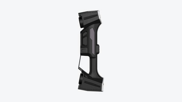
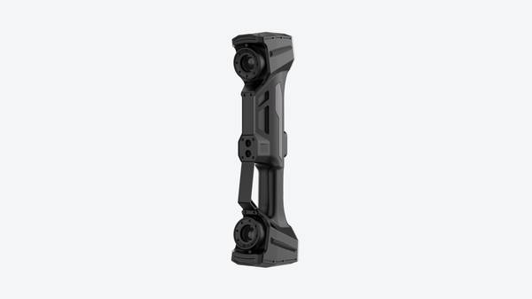
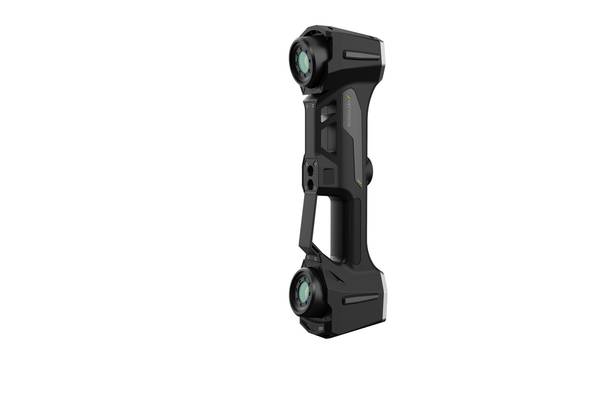
INSVISION designs its AlphaVista large-format handheld 3D scanner to perform under these exact on-site constraints, not just controlled lab benchmarks.
Evidence-Based Validation Criteria for Industrial 3D Scanners
Most quality teams have learned the hard way that glossy spec sheets and lab-generated data rarely translate to reliable performance on a factory floor. When a 3D scanner is being evaluated for large-part applications—oversized weldments, composite layup tools, aircraft structural components—the validation framework needs to be built around reviewable, field-tested evidence, not marketing claims.
For INSVISION systems like the AlphaVista, this means starting with full-geometry scan coverage: can the scanner capture the entire surface of an oversized assembly without requiring multiple stitching setups that accumulate error?
Measurement repeatability must be checked across different operators and shift cycles, because a gage R&R study that only involves one experienced user in a quiet lab tells you nothing about production reality. Surface-type consistency is another overlooked variable—castings, machined faces, and dark composite skins all respond differently, and the validation should happen on the actual materials running through your facility.
Equally critical is native compatibility with your existing QMS and GD&T reporting software; if scan data requires manual translation or re-formatting, traceability degrades. Audit-ready data traceability for every scan project, including timestamped raw data, operator ID, and alignment records, is non-negotiable in ISO/ASME environments.
Above all, the quality lead should insist on on-site sample scans using the buyer’s own parts and tolerance requirements. Pre-arranged vendor demos with pristine artifacts prove nothing. Run it on your most demanding geometry, in your ambient conditions, with your operators, and then compare the output to your CMM or laser tracker baselines. That’s the only evidence that matters.
A Standardized Workflow for Large-Part 3D Scanning Validation
Most validation protocols start with a single accuracy figure printed on a datasheet. That approach falls apart fast when you’re measuring a 2-meter weldment or a composite layup tool under a shop floor that cycles 15°F between morning and afternoon. A number that holds in a climate-controlled lab tells you nothing about what your 3D scanner will actually deliver on your part, in your environment, with your operators.
The right way is a structured, audit-aligned validation workflow that quality teams can run themselves. We break it into four phases. First, pre-scan assessment: map the part’s geometry, flag surface finishes that risk laser scatter, and scale your reference marker strategy to the part size—big parts need fewer, larger, and more stable targets.
Second, on-site data capture: run a standardized scan pass structure, deliberately introduce a second operator to test variability, and log ambient temperature, vibration, and lighting conditions. Third, post-processing alignment: check inter-pass registration error against a defined tolerance before you lock the dataset, then align the whole scan to the CAD model.
Fourth, reporting: run GD&T deviation analysis against ASME Y14.5 callouts and generate a traceable output package that both quality and engineering can review and sign off on.
How INSVISION AlphaVista Aligns With Evidence-Based 3D Scanning Standards
When you’ve already validated a scanner’s accuracy on a calibrated artifact, the real question is: will it hold that performance under the boundary conditions your parts actually create—overhead reaches, mixed-surface finishes, and shop-floor vibration?
For quality teams that need reviewable, consistent results rather than a spec-sheet headline, the INSVISION AlphaVista large-format handheld 3D scanner is built to answer that directly.
The AlphaVista’s handheld form factor lets an inspector reach into recessed pockets and scan upward-facing features on large, immovable assemblies without rigging—a real-world requirement that many tripod-mounted systems fail. Its wide scan coverage per pass reduces the total number of alignments, cutting the accumulated error that makes long, feature-rich surfaces hard to stitch.
On surfaces that would normally demand developer spray or masking, the system maintains consistent data capture across machined aluminum, as-cast textures, and glossy composites, often eliminating the need for extensive pre-treatment.
Finally, the scan delivers exportable, traceable point cloud and mesh data that integrates directly with standard quality and CAD software, so every GD&T callout and first-article report can be traced back to a verifiable measurement set. That’s the kind of evidence-based validation a quality lead can actually take to an audit.
Setting Realistic Deployment Boundaries for Large-Format 3D Scanning
When does a large-format handheld 3D scanner actually earn its keep on the shop floor, and when does a simpler measurement tool do the job just as well? That question sets the boundary conditions every quality team needs to pin down before pulling the trigger on a capital investment. The clearest operational value shows up in a handful of inspection tasks where scale, access, and the need for dense surface data converge.
Large-format handheld scanning is best suited for first-article inspection of large composite aerospace components — wing skins, fairings, and fuselage sections where hard-gauge setups would take days and CMM travel limits become a bottleneck.
It is best suited for on-site dimensional verification of automotive body-in-white assemblies, where you need to capture flush-and-gap conditions and surface deviations across a full side frame without moving the part off the line.
It is best suited for reverse engineering of legacy MRO parts for energy infrastructure — think turbine housings or pump volutes with no original CAD, where every blended surface and as-cast deviation matters.
And it is best suited for in-process quality checks on large welded structural components, like bridge girders or heavy equipment frames, where you need to verify weld-distortion trends before they stack up across multiple joints.
The evidence that matters is not a spec sheet number. It is a sample scan run on your own part, with your own tolerance requirements, in your own lighting and vibration conditions. That is the only reliable way to confirm fit.
INSVISION’s AlphaVista, for example, is designed to capture large surfaces quickly, but the real question is whether the point spacing, volumetric accuracy, and scan-to-CAD workflow align with what your inspection reports demand. A vendor lab demo tells you something; a targeted sample scan on a known artifact with GD&T callouts tells you what you need to know.
Insist on a reviewable output — a color map, a deviation report, a verified mesh — that you can evaluate against your internal standards. If the tool cannot deliver that in a half-day test, it is unlikely to deliver it in full production.
Ultimately, the most reliable way to drive value from a 3D scanner investment is to match tool capabilities to the specific on-site constraints you actually face, not to the single largest accuracy spec or scan volume number on a data sheet. A scanner that handles long-range, large-surface capture with minimal targets might be perfect for a wind turbine blade but overkill for a brake caliper bracket.
Define the worst-case part size, the tightest tolerance you need to hold, and the environmental conditions — dust, vibration, temperature swings — before you evaluate anything.
Hangzhou Insvision Technology Co., Ltd.
Address: Building 1, No. 1399 Liangmu Road, Yuhang District, Hangzhou, Zhejiang 311121, China
Copyright © Hangzhou Insvision Technology Co., Ltd. All rights reserved.
Copyright © Hangzhou Insvision Technology Co., Ltd. All rights reserved.