

Understanding the 3D Scanner for Small Objects and the Full-Surface Inspection Workflow It Enables
Understanding the 3D Scanner for Small Objects and the Full-Surface Inspection Workflow It Enables. The underlying principle is optical triangulation.
Throughout, we’ll refer to INSVISION’s technology approach — particularly the AlphaVista and AlphaScan platforms — to illustrate how a measurement tool moves from scanning a part to generating an actionable quality report.
What a 3D Scanner for Small Objects Actually Does
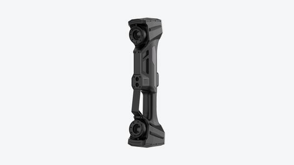
A 3D scanner for small objects is a metrology device that captures the three-dimensional shape of a component by projecting a known light pattern onto its surface and observing how the pattern deforms from one or more camera viewpoints. The underlying principle is optical triangulation. A projector emits a sequence of fringe patterns, and the cameras record the reflections.
Because the geometric relationship between the projector and the cameras is precisely calibrated, the system can compute the X, Y, Z coordinates of every point on the visible surface. The output is a dense point cloud — often millions of points — that represents the part’s as-built geometry.
Scenario Snapshot
A practical way to read the article is through this scenario:
- What a 3D Scanner for Small Objects Actually Does: A 3D scanner for small objects is a metrology device that captures the three-dimensional shape of a component by p…
- How the Data Becomes an Inspection Report: The value of scanning is not in the point cloud itself — it’s in the traceable dimensional report that follows.
- Where Traditional Measurement Falls Short: A touch-trigger CMM is accurate, but it samples geometry sparsely.
What separates a metrology-grade scanner from a generic 3D camera is the combination of calibrated optics, strict thermal stability, and software that reconstructs surfaces with documented uncertainty. For small parts, the scanner must resolve tiny features: a 0.3 mm notch, a micro-textured surface, or a laser-etched serial number.
This demands a compact measurement volume, high camera resolution, and illumination that minimizes shadowing in recesses. The resulting data is not just a visual model; it can be aligned to the nominal CAD model and analyzed with GD&T software to produce a full deviation color map, profile of a surface evaluations, and automated pass/fail determinations.
How the Data Becomes an Inspection Report
The value of scanning is not in the point cloud itself — it’s in the traceable dimensional report that follows.
- Scan acquisition. The part is placed on a fixture or rotary stage, and the scanner captures multiple exposures from different angles. The software stitches these into a single, watertight mesh.
- Alignment. The scan data is aligned to the CAD reference using a best-fit or feature-based method, establishing the coordinate system.
- GD&T evaluation. The mesh is compared to the nominal geometry. Deviations are displayed as a heat map, and specific callouts — diameter, flatness, position, profile — are extracted automatically.
- Reporting. The system generates a report that includes deviation values, pass/fail status, and traceability information such as part serial number, operator ID, and timestamp.
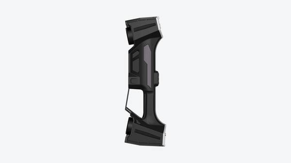
INSVISION’s ecosystem illustrates how this chain can remain unbroken. The AlphaVista large-format handheld scanner is often used for full automotive sensor modules, capturing the overall assembly and its mating interfaces.
When a flagged defect points to a tiny internal housing, a quality technician can transfer that same housing to an AlphaScan station — a 3D scanner for small objects calibrated for tight-tolerance components. The small-part scan exports directly to the shared GD&T tool, overlaying on the nominal model and flagging deviations in wall thickness, flatness, and mounting hole runout.
The final report auto-populates with traceability IDs, ready for ISO 9001 audit trails, and can be cross-referenced with production parameters from the MES.
Where Traditional Measurement Falls Short
A touch-trigger CMM is accurate, but it samples geometry sparsely. When a small part has continuously curving surfaces, blend radii, and subtle draft angles, probing a few dozen discrete points leaves the vast majority of the surface unverified. A 2D vision system may capture an edge profile quickly, but it cannot measure the profile of a freeform surface in three dimensions.
The result is a data gap that often forces engineers to accept risk they cannot quantify.
Optical 3D scanning changes the equation. A dense point cloud captures the full surface, making it possible to detect a shallow sink mark, a ripple across a sealing face, or a slight taper in a bore that a CMM probing strategy might miss. The comparison is not about which instrument is “more accurate” in absolute terms;
it’s about the completeness of the data and the speed with which it can be obtained directly on the shop floor.
The table below summarizes the key differences in a typical small-part inspection context.
| Assessment Dimension | Traditional Spot Measurement | 3D Scanning for Small Objects |
|---|---|---|
| Data density | A few to a few hundred discrete points | Millions of points covering the entire surface |
| Geometry capture | Well-suited for prismatic features | Handles freeform, organic, and complex surfaces |
| Surface deviation detection | Limited to probed locations | Full-field color map reveals subtle form errors |
| Cycle time for first-article inspection | Often requires fixture programming and long run times | Scan acquisition in minutes, with automated reporting |
| Shop-floor suitability | Requires stable environment and skilled programming | Portable systems can be deployed next to the production cell |
When a 3D Scanner for Small Objects Is the Right Fit — and When It Isn’t
A 3D scanner for small objects excels in high-mix, tight-tolerance environments where part geometries change frequently and the measurement task goes beyond simple prismatic checks.
- First-article inspection of micro-molded parts with complex freeform surfaces.
- In-process verification of medical device fasteners or micro-brackets where 100% dimensional sampling is impractical.
- Tooling wear analysis, where the entire surface of a mold cavity must be compared to the original CAD to detect progressive erosion.
- Reverse engineering of legacy components for which no drawing exists.
However, scanning is not a universal replacement. Parts with deep, narrow blind holes or highly reflective, mirror-like surfaces can challenge optical systems without proper preparation. Transparent or translucent materials require coating with a thin, removable layer of scanning spray.
If the inspection task is limited to a few critical diameters and the part geometry is purely prismatic, a well-programmed CMM or a dedicated hard gage may still be the more economical choice. The decision hinges on the complexity of the surface, the required data density, and the acceptable cycle time.
Practical Selection Considerations
Before bringing a system in-house, engineers should evaluate it against real production parts, not generic demo blocks. A 3D scanner for small objects must prove it can capture the smallest critical feature reliably. That means scanning a micro-machined notch or a laser-etched identifier across multiple parts and checking for data dropouts.
The end-to-end data handoff deserves equal scrutiny: generate a deviation report and confirm it imports directly into the existing QMS without manual reformatting. Time the full cycle, including part fixturing and report generation, to ensure it aligns with the station’s takt requirement.
Other evaluation points include:
- Volumetric accuracy. Review the manufacturer’s stated accuracy under real-world thermal conditions, and verify that it is supported by a traceable calibration artifact.
- Software ecosystem. The scanner should interface with the GD&T and statistical process control tools already in use.
- Ease of use. The operator interface should allow a quality technician, not just a metrology specialist, to run a repeatable measurement routine.
- Service and support. Confirm that local calibration and application support are available to keep measurement uncertainty under control over time.
INSVISION’s Approach: From Large-Format Scanning to Small-Part Detail
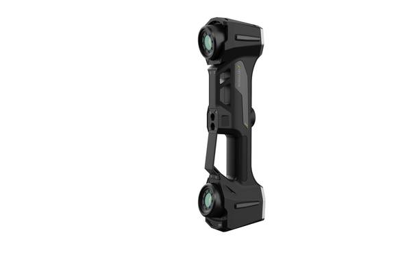
INSVISION’s product line addresses the full inspection workflow rather than a single scanning task. The AlphaVista handheld scanner is designed for large-format, high-resolution scanning of assemblies and sub-systems. Its broad field of view and rapid capture speed make it practical for scanning a complete automotive sensor module or a medical device housing directly on the shop floor.
When a detailed analysis of a small internal component is required, the AlphaScan — a dedicated 3D scanner for small objects — provides the tighter measurement volume and higher point density needed for features in the sub-millimeter range.
Both systems feed into a common software environment, meaning that a deviation detected on a large assembly can be traced down to a micro-feature on a subcomponent without switching software platforms or reformatting data.
This integrated approach removes the silos that often separate large-part and small-part inspection. The quality report becomes a single thread of evidence, from the full assembly scan to the discrete small-part verification, all linked by traceability identifiers. For quality managers operating under ISO 9001 or AS9100, this continuity significantly reduces the administrative burden of maintaining separate inspection records.
Common Misconceptions and Technical Q&A
Q: Can a structured-light scanner measure internal features like deep small bores?
Hangzhou Insvision Technology Co., Ltd.
Address: Building 1, No. 1399 Liangmu Road, Yuhang District, Hangzhou, Zhejiang 311121, China
Copyright © Hangzhou Insvision Technology Co., Ltd. All rights reserved.
Copyright © Hangzhou Insvision Technology Co., Ltd. All rights reserved.