

Industrial 3D Scan to STL Costs More in Rework Than in Hardware
Industrial 3D Scan to STL Costs More in Rework Than in Hardware. For many quality and operations teams, the scanner purchase is the easy part.
For many quality and operations teams, the scanner purchase is the easy part. The harder cost question is whether the resulting mesh can move into inspection, toolmaking, or additive workflows without absorbing skilled labor. A 3D scan to STL file is not an end product. It is a data deliverable.
When that file arrives with alignment drift, false bridging, or low point density in critical areas, engineers spend hours repairing geometry that should have been captured correctly.
The result is a familiar cost pattern: capital equipment adds capability, but the old labor and rework burden shifts from the shop floor to the CAD workstation.
This article maps where that rework comes from and how production managers, quality leads, and cost owners can evaluate a 3D scan to STL process before it reaches production.
Where the Rework Problem Actually Starts
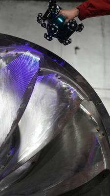
A scanner that passes a calibration test in a controlled lab can still produce a poor 3D scan to STL result on a production floor. The published accuracy figure typically reflects reference conditions: stable temperature, clean geometry, controlled surface finish, and minimal vibration.
Scenario Snapshot
A practical way to read the article is through this scenario:
- Where the Rework Problem Actually Starts: A scanner that passes a calibration test in a controlled lab can still produce a poor 3D scan to STL result on a p…
- The Operating Cost Is in Cleanup, Not Capture: Traditional measurement costs tend to hide in skilled labor, setup time, machine downtime, and the wait for inspec…
- A Field-Based Cost Framework for 3D Scan to STL Out…: Instead of comparing catalog accuracy alone, operations teams can evaluate the total cost of a usable mesh.
Production parts rarely offer those conditions.
Shiny aerospace alloys create speckle dropout. Carbon fiber weave absorbs or scatters laser energy unevenly. Textured medical polymers soften edge definition. Deep pockets and undercuts force poor sensor incidence angles, leaving mesh gaps or false bridging. On large assemblies, vibration from adjacent equipment and movement of the part or fixture can introduce low-level noise into the raw scan data.
None of this is visible on a calibration certificate. It becomes visible only when the STL mesh is overlaid on CAD, compared in CMM software, or sliced for tooling or additive work.
Consider a first-article inspection on a cast housing. The scan appears dense and complete on screen, but the exported 3D scan to STL contains a filled pocket because the scanner could not reach the bottom of a deep bore. Software bridged the opening. The CMM comparison flags it later. At that point, the inspection schedule resets and an experienced technician spends time isolating the problem.
The Operating Cost Is in Cleanup, Not Capture
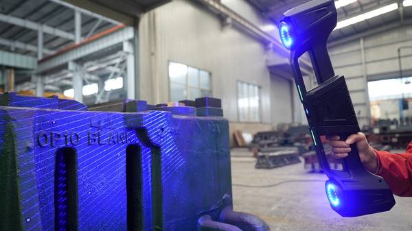
Traditional measurement costs tend to hide in skilled labor, setup time, machine downtime, and the wait for inspection results. A hand layout on a large weldment may tie up a senior inspector and a surface plate for hours. CMM programming can require careful alignment and multiple iterative runs.
3D scanning can reduce much of that time. But if the 3D scan to STL output is not production-ready, the cost does not disappear.
- Repairing mesh holes and false surfaces
- Re-aligning scan patches that have drifted
- Re-scanning sections that could not be captured reliably
- Re-checking filled areas against the part or CAD model
- Re-formatting files for CMM, CAD, or slicer use
Those tasks consume engineering hours and delay first article inspection, tool tryout, or reverse engineering deliverables. For many plants, that labor cost is the real economic factor in a scanning workflow. The scanner hardware is a fixed cost. The time required to make the mesh usable is a repeating cost.
A Field-Based Cost Framework for 3D Scan to STL Output
Instead of comparing catalog accuracy alone, operations teams can evaluate the total cost of a usable mesh. The evaluation should happen on the production floor, with real parts and the actual downstream software.
| Evaluation Point | What to Check | What It Affects |
|---|---|---|
| Production part geometry | Scan cast, machined, and shiny surfaces together. Check edge sharpness, deep features, and whether the mesh is complete. | Manual hole filling, CMM discrepancy time, and re-scan frequency |
| Tracking stability | Scan a large part or assembly in one session. Look for seams, step errors, and patch mismatch. | Alignment labor, scan session reliability, and mesh cleanup hours |
| Export readiness | Open the STL in CAD, CMM software, and a 3D printing slicer. Note any repair or conversion steps. | Skilled engineering time and downstream delivery cadence |
| Repeatability | Have multiple operators scan the same part across sessions. Compare deviation maps. | First article consistency, audit confidence, and recurring inspection cost |
| Traceability | Confirm whether the system records alignment information for each scan session. | Non-conformance investigation time and customer quality evidence |
The key question is not whether the scanner can produce a dense point cloud. It is whether the resulting 3D scan to STL file can enter the existing quality and manufacturing process without becoming a project.
Qualitative cost logic can help here. A plant can assess total scan-to-STL cost as the sum of hardware access cost, mesh cleanup labor, downstream re-inspection time, and delivery delay. The target is not the lowest purchase price. The target is the lowest total cost of a mesh that is usable on the first release.
Where INSVISION V-Track Fits the Cost Conversation
For large castings, weldments, and composite layup tools, a central failure point in a 3D scan to STL workflow is alignment drift across the scan volume. If intermediate scans are not locked to a stable reference, the final mesh shows step errors and surface mismatch that require manual cleanup before inspection or CAM.
INSVISION V-Track addresses that problem with a tracking-based architecture. The system holds a fixed spatial reference while the operator moves around the part. That helps keep alignment consistent across the full scan volume, even on long or geometrically complex components.
From an operational perspective, that capability matters because it reduces the likelihood of manual alignment work after scanning. Instead of spending time repairing patch boundaries, the quality team can move into section comparison, CAD overlay, and tolerance evaluation.
V-Track also supports a practical validation path. Before releasing the workflow, a plant can scan a golden part or first article sample, review the alignment record, check sectioned mesh profiles against CAD, and confirm that the STL exports cleanly into existing inspection, CAD, or additive software.
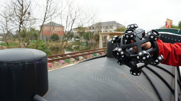
For aerospace and medical device programs, the alignment record can also serve as audit evidence. That shifts the scan output from an unchecked mesh into a reviewable quality record, which reduces the time required to demonstrate process control.
First Scenarios for Operational Rollout
A practical rollout should start with two or three constrained scenarios where the cost of rework is high and the value of reliable mesh output is easy to observe.
Large or long assemblies. Parts that require multiple scanning positions or long scan paths are the most exposed to tracking drift. A production trial on a large weldment, frame, or composite tool can quickly reveal whether alignment remains stable across the full volume.
On-site measurement tasks. When a part cannot easily move to a measurement lab, scanning must work in the field. Flexible deployment with stable tracking reduces the material handling and setup steps that often inflate inspection time.
Recurring inspection or reverse engineering. Jobs that repeat over multiple parts or batches benefit most from consistent, traceable 3D scan to STL output. The validation effort on the first article pays back over the subsequent runs because the process no longer starts from zero.
In each case, the pilot should use actual production parts, not polished lab samples. Scan machined faces, cast textures, and edge transitions. Check the exported mesh in CAD, CMM, and slicer environments. Run the same scan with different operators. Write down the pass/fail thresholds and keep the records for ISO/ASME GD&T traceability.
That approach turns a scanner evaluation from a specification review into a production capability test.
The Real Investment Decision
A 3D scan to STL workflow is not valuable because a scanner was purchased. It is valuable because the mesh moves through inspection, tooling, or additive production without creating a new source of engineering labor.
For plant leaders, the evaluation should therefore focus on rebuild time, alignment labor, audit readiness, and delivery risk—not just scanner accuracy. A controlled field validation program identifies those cost issues early, before the workflow hardens into a recurring problem.
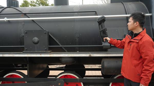
The most useful output is not a dense point cloud. It is a production-ready mesh that the quality system can trust.
Hangzhou Insvision Technology Co., Ltd.
Address: Building 1, No. 1399 Liangmu Road, Yuhang District, Hangzhou, Zhejiang 311121, China
Copyright © Hangzhou Insvision Technology Co., Ltd. All rights reserved.
Copyright © Hangzhou Insvision Technology Co., Ltd. All rights reserved.