

What a Handheld 3D Scanner Workflow Actually Delivers in Production Quality
Automotive tier-one component checks, aerospace MRO part validation, and medical device implant inspection still often rely on manual gauges plus fixed CMMs.
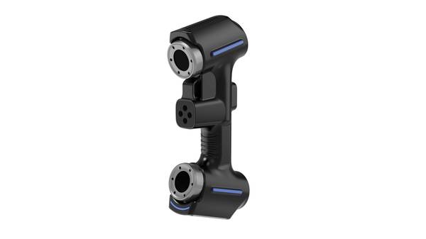
Across discrete manufacturing, dimensional inspection has been moving out of the controlled metrology lab and into production cells. Automotive tier-one component checks, aerospace MRO part validation, and medical device implant inspection still often rely on manual gauges plus fixed CMMs. The result is that quality, process engineering, and production teams frequently work from different data snapshots of the same part.
A 3D scanner handheld on the shop floor changes that split. Instead of moving parts to a measuring machine, the operator captures dense point clouds at the workstation, aligns the scan to CAD or GD&T callouts, and pushes color deviation views into a shared review loop.
This article explains how the workflow actually functions, where it fits, and what to validate before building a scan-to-report process around a handheld 3D scanner.
What a Handheld 3D Scanner Actually Measures
A handheld 3D scanner works by projecting a structured light pattern or laser line onto a surface and recording how that pattern deforms across the part geometry. The system converts the observed distortions into three-dimensional coordinates, building a point cloud as the operator moves the device around the object.
The principle is not fundamentally different from fixed structured light or laser scanning systems. The difference is portability and path flexibility. The operator can walk around a large assembly, change approach direction for deep bores or undercuts, and keep scanning parts that cannot easily be repositioned.
What the scanner produces is dense surface data. That data becomes useful only after it is aligned to a reference CAD model or master scan and interpreted against tolerance zones. In practice, the scanner is the data collection front end. The workflow around it determines whether the output becomes an inspection record, a process insight, or simply another unread point cloud.
Why the Handoff Matters More Than the Hardware
A common misconception on the shop floor is that scan repeatability starts with the scanner. In most shop-floor inspection workflows, the larger sources of variation are introduced before the first frame is captured.
For small precision components, a magnetic or pin-locating nest that constrains all six degrees of freedom keeps part position stable during scanning. Large assemblies need supports placed near datum features rather than at mid-span points where gravity can create subtle movement. Reflective or textured surfaces require uniform matting or powder coverage.
If film thickness is not negligible relative to the tolerance band, it becomes a source of error that no scanner can correct in post-processing.
Quality and process engineering teams should also align on ASME GD&T or ISO 1101 before scanning begins. Specifically, they need to agree on which features carry functional tolerance. That alignment removes downstream disputes over whether a deviation map represents a real non-conformance or a difference in interpretation.
Scan Path Execution and Coverage Validation
The key to a complete handheld scan is not simply painting the part with the scanner. It is validating coverage while the operator still owns the surface.
A handheld 3D scanner works best when the scan path is planned around feature orientation rather than a single straight pass. For undercuts, deep bores, and free-form curved surfaces, the operator should change approach direction and roll the scanner head so the laser or structured light pattern stays near normal incidence. Shallow grazing angles add noise and create false shadows in the point cloud.
The live preview is the first quality gate. Thin, missing, or noisy patches should be reacquired before post-processing, while the part is still in position. This matters most for installed aerospace structure or large automotive stamping dies that cannot be repositioned. It also reduces the cost of discovering an incomplete scan after the physical setup has already been broken down.
From Point Cloud to Deviation Report
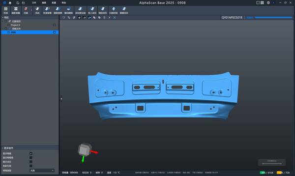
Raw scan data rarely goes straight into a report. The post-processing loop starts with automated cleaning that strips stray points and sensor noise, followed by mesh generation. After that, the mesh is aligned to the reference CAD model using common datum features such as machined bores, tooling faces, or locating pads. That alignment is what ties the comparison back to the same GD&T callouts on the drawing.
Feature-based deviation mapping then shows exactly where a surface falls outside tolerance, rather than relying on an overall pass/fail number. A color-coded map becomes the shared visual reference: green marks in-tolerance surfaces, while red and blue flag excess material or undercut conditions.
This dataset is also where cross-team work happens. Quality engineers use the aligned deviation map for first-article inspection sign-off. Process engineers pull the same file into their own review and look for repeated deviation patterns across later batches. Production teams can open the scan when a non-conformance appears and check whether the cause is fixture offset, part loading, or a setup issue.
The practical value of a shop-floor 3D scanner handheld workflow is that all three groups work from one version of the dimensional truth. That removes much of the manual transcription and disconnected photo evidence that often slow down exception review.
Handheld Scanning Compared with Fixed CMM and Other Methods
The choice between a handheld 3D scanner and a fixed CMM is not about one method being universally better. It is about access, part geometry, and the required data deliverable.
| Evaluation factor | Fixed CMM | Handheld 3D scanner |
|---|---|---|
| Typical deployment | Metrology lab or controlled room | Production cell or MRO station |
| Part access | Parts must fit within machine envelope | Operator moves around the part |
| Data output | Discrete touch points or scan data | Dense surface point cloud |
| Large or installed parts | Often impractical to measure | Practical if operator can access surfaces |
| Requirement for stable setup | Machine provides controlled motion | Operator path and part fixturing matter more |
| Common fit | Tight-tolerance prismatic features, repeat measurement | First-article inspection, large surfaces, MRO, in-process checks |
A handheld 3D scanner is not a direct replacement for a CMM when the tolerance range is tighter than the scanner’s validated uncertainty for a given feature size. But it fills a different production need: capturing enough surface data quickly, near the process, without disassembling or transporting the part.
Where the Workflow Fits and Where It Does Not
The workflow is well suited to first-article inspection, in-process deviation checks, non-conformance resolution, and MRO part validation. It is particularly practical for large assemblies, installed components, and high-mix, low-volume production where moving parts to a metrology lab creates downtime.
The workflow is less appropriate when the inspection task demands extremely tight tolerances on small prismatic features, or when the part surface cannot be prepared without changing the measured dimension. Highly reflective, transparent, or deep internal geometries also require careful validation before deployment.
In those cases, a controlled CMM, touch probe, or alternative gaging method may still be the better primary inspection tool. The handheld scanner can serve as a complementary tool for surface deviation and as-built documentation.
Selection Considerations for a Shop-Floor 3D Scanner Handheld
When evaluating a handheld 3D scanner for production inspection, the discussion should start with the scan object and the required data deliverable, not the specification sheet.
Key evaluation areas include:
- Feature size and tolerance range: Validate the scanner on reference artifacts that match the smallest features to be inspected.
- Surface finish and preparation: Confirm that matting or powder, if required, does not shift the measurement beyond tolerance.
- CAD alignment workflow: Check how the software aligns scan data to datum features and GD&T callouts.
- Data export and traceability: Review how the system connects to quality management systems and whether scan evidence can be referenced by each reported deviation.
- Coverage validation: Look for live feedback that shows missing or noisy areas before the operator moves away from the part.
A practical validation step is to run a reference artifact correlation or gage R&R study before deployment. That tells the team how repeatable the system is on the specific feature sizes, surface finishes, and tolerance bands involved.
INSVISION AlphaScan in the Scan-to-Report Loop
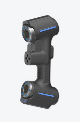
The INSVISION AlphaScan handheld 3D scanner fits into this workflow as a shop-floor data acquisition tool. It can be set up directly at the production cell or MRO station, so parts do not need to travel to a dedicated metrology lab for routine inspection.
From a process perspective, the AlphaScan supports the scan-to-report loop in three areas. First, it provides on-board coverage verification so incomplete scans can be corrected while the part is still in position. Second, it generates standardized data outputs that connect to common quality management systems, which reduces manual transcription errors.
Third, the resulting deviation map and GD&T callout summary give quality, process engineering, and production a shared review file instead of conflicting spreadsheet reports.
The product value is not only in capturing points. It is in shortening the handoff between scanning, review, and disposition when a deviation is found.
Common Misconceptions and Technical Q&A
Is a handheld 3D scanner repeatable enough for shop-floor inspection?
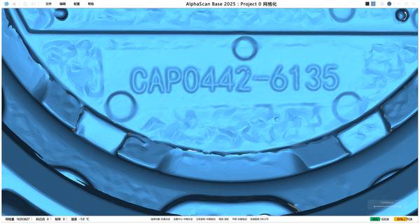
Repeatability depends on fixturing, scan path, surface preparation, and validation on the specific feature sizes involved. The practical question is not whether handheld scanning can be repeatable, but whether it has been validated against a reference artifact for the intended tolerance band.
Does the scanner replace GD&T knowledge?
No. The scanner captures surface geometry, but alignment and tolerance interpretation still require engineering decisions about datums, functional features, and ASME or ISO callouts.
Can the scan data go directly into a first-article report?
Usually not raw. The point cloud must be cleaned, meshed, aligned to CAD, and converted into deviation maps tied to specific callouts. The reportable deliverable is the traceable package, not the raw mesh.
Does every non-conformance need a rescan?
Rescanning is most useful when the first scan is incomplete or when the part has changed state. More importantly, reinspection triggers should be defined by process risk: tool change, first-piece setup, non-conformance correction, and MRO rework are common events where a controlled rescan makes sense.
Summary
A 3D scanner handheld changes the shop-floor inspection loop by moving data collection closer to the part and giving multiple departments a shared deviation view. The scanner itself is not the full answer. The quality of the result depends on pre-scan setup, scan path discipline, CAD alignment, tolerance alignment, and how the deviation data is handed off for review.
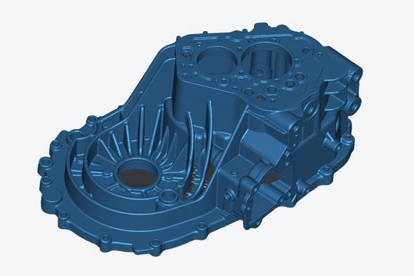
For production teams that need fast surface documentation, first-article review, or MRO validation without relocating parts, the INSVISION AlphaScan handheld 3D scanner provides a practical fit. The key is to treat it as part of a controlled scan-to-report workflow rather than as a stand-alone measurement device.
Hangzhou Insvision Technology Co., Ltd.
Address: Building 1, No. 1399 Liangmu Road, Yuhang District, Hangzhou, Zhejiang 311121, China
Copyright © Hangzhou Insvision Technology Co., Ltd. All rights reserved.
Copyright © Hangzhou Insvision Technology Co., Ltd. All rights reserved.