

3D Scan to STL: Why a Scanners Accuracy Spec Isnt Enough
3D Scan to STL: Why a Scanners Accuracy Spec Isnt Enough. The STL (stereolithography) format tessellates that cloud into a triangle mesh.
What “3D Scan to STL” Really Means
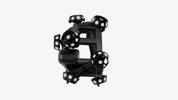
A 3D scanner captures point clouds—sets of X, Y, Z coordinates representing surfaces. The STL (stereolithography) format tessellates that cloud into a triangle mesh. Converting a 3D scan to STL is not a simple file export; it is a chain of decisions: alignment, noise filtering, meshing parameters, and hole-filling. Each link can distort the final geometry.
Key Points at a Glance
- A 3D scanner captures point clouds—sets of X, Y, Z coordinates representing surfaces.
- Any metrology engineer knows that a measurement system’s performance is inseparable from its environment.
- Building confidence in a 3D scan to STL output requires a validation protocol that mirrors the actual production environment.
- Not all alignment methods are equal.
The central misconception is that scanner accuracy equals STL accuracy. A scanner’s single-point precision, measured under lab conditions, describes the uncertainty of one coordinate. It says nothing about how well hundreds of thousands of points will align when the part is scanned from multiple positions, on a vibrating floor, under changing ambient light.
Deployment Validation Checklist
| Focus Area | Decision Point | Deployment Note |
|---|---|---|
| Target part | Check size, surface condition, and key tolerances against the scan task | Run a full trial scan on a representative part |
| Data workflow | Verify point cloud, deviation map, and quality-report handoff | Confirm export formats and review ownership in advance |
| Shop-floor use | Review training, calibration, lighting, and working space | Keep the validation record as a repeatable inspection reference |
The STL inherits not only the scanner’s native resolution but also the cumulative errors of registration, environmental drift, and post-processing.
Key Variables That Laboratory Specs Ignore
Any metrology engineer knows that a measurement system’s performance is inseparable from its environment.
- Surface behavior: Polished aerospace alloys cause specular reflections that saturate sensors. Translucent medical polymers scatter light, producing phantom point density. Dark or matte surfaces can starve the sensor of return signal. A scanner’s lab spec, measured on a matte ceramic artifact, tells you nothing about how it handles these real materials.
- Part geometry and occlusions: Undercuts, deep pockets, and sudden section changes create shadow zones. A single-pass scan will leave gaps that the meshing algorithm must guess at. The more complex the geometry, the more those guesses compound.
- Alignment strategy: Most scanners rely on either target stickers or feature-based registration to stitch successive scans. On large, smooth stamping dies or repetitive blisk blades, feature matching can mis-register, introducing a low-frequency undulation across the entire STL. This error is invisible to a local point-spacing check but fatal to a GD&T profile tolerance.
- Environmental instability: Forklift traffic, thermal expansion, and ambient light shifts all introduce drift during a scan sequence. A lab spec measured on a granite table in a temperature-controlled room simply does not apply.
- Post-processing artifacts: Over-aggressive noise reduction can erase fine edges and radiused corners. Automatic mesh decimation can simplify critical features out of tolerance. These are software decisions, not scanner performance, yet they define the STL that goes to inspection.
Because these variables interact, evaluating a 3D-scan-to-STL solution by a single spec—nominal accuracy, point density, or scan speed—is like judging a machining center solely by its spindle RPM. The output mesh is a system property, not a sensor property.
How to Validate a Scan-to-STL Pipeline for Industrial Use
Building confidence in a 3D scan to STL output requires a validation protocol that mirrors the actual production environment. Relying on a spec sheet alone is not auditable.
- Reference artifact testing: Scan a calibrated artifact of known dimensions—ideally traceable to NIST or an equivalent national metrology institute—using the same setup, fixtures, and operator cadence deployed on production parts. Compare the resulting STL to the artifact’s certified values. This provides a baseline for measurement traceability in your workflow, not in the vendor’s demo room.
- Multi-operator repeatability: Run the same scan with different operators and across multiple shifts. If the STL mesh shifts beyond the acceptable tolerance band, the process is inconsistent. No increase in scanner resolution will fix an unstable alignment chain.
- GD&T verification directly on the mesh: Avoid the common shortcut of a best-fit surface deviation color map. Instead, measure flatness, profile, position, and runout on the STL exactly as you would on a first-article inspection. If the software cannot support datum alignment and tolerance evaluation on the mesh, the STL is not ready for inspection-level work.
- Audit trail reconstruction: A quality auditor should be able to trace the STL back to the raw scan data. This means documented alignment targets, processing parameters, environmental conditions, and operator logs. If the metadata chain is broken, the dataset is not auditable—an unacceptable risk for ISO 9001 or AS9100 environments.
These steps are not aspirational. They are the minimum for converting a 3D scanning system into a reliable metrology tool.
Where Tracking-Based Architecture Changes the Equation
Not all alignment methods are equal. Traditional scan-to-STL workflows rely on post-hoc software registration: the scanner captures frames, and an algorithm aligns them using part geometry or target stickers. For parts over a meter in length, or with sparse features, cumulative error becomes the dominant uncertainty.
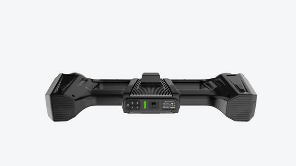
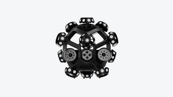
INSVISION’s V-Track system uses a real-time optical tracker that continuously monitors the scanner’s position relative to the part. Each captured frame is locked into a common coordinate system during acquisition, not stitched afterward. This architectural difference means that alignment drift does not accumulate over long scan sequences.
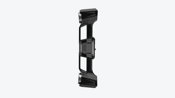
The resulting point cloud is intrinsically registered, and the STL surface faithfully represents the as-built geometry without the low-frequency undulation that can plague feature-based alignment on large, smooth components.
The tracker also logs the position and timestamp of every frame. This creates an auditable record that ties each triangle in the STL back to its capture moment. For aerospace MRO, where components are often scanned in situ and reassembled later, this traceability allows verification that the entire scan volume was covered without gaps, and that the STL was generated from optically tracked data, not inferred stitching.
The V-Track approach is particularly advantageous when geometry is repetitive or sparse. Automotive stamping dies with long, featureless surfaces can confuse registration algorithms that match based on shape. A turbine blisk with many similar blades presents the same challenge. By referencing the external tracker, the system avoids false matches and keeps the STL globally consistent.
Practical Boundaries: When Higher Resolution Doesn’t Help
A common misstep is to assume that higher point density always yields a better STL. In reality, excessive density increases processing time, file size, and noise, often without improving the functional quality of the mesh. For a cast part with a ±0.5 mm profile tolerance, a 0.05 mm point spacing adds no measurement value; it simply creates a larger, noisier file that is harder to work with.
The correct approach is to match density to the tolerance requirements of the application. Define the smallest geometric detail that must be resolved, and set scan parameters accordingly. INSVISION’s scanning workflows allow users to control point density based on the inspection task, not just the scanner’s maximum capability.
This keeps STL files lean and computationally manageable without sacrificing the feature resolution needed for GD&T verification.
Similarly, tracking-based systems like V-Track are best suited for large or complex parts where consistent alignment across multiple scan passes is a priority. They eliminate the need for manual target placement, which slows large-volume work. But no single solution fits every application. Parts that are small, self-contained, and easily fixture-mounted may be adequately served by a desktop structured-light scanner.
The key is to validate on-site, with your own parts and tolerances, rather than assuming a technology’s published capability will transfer unchanged.
Common Misconceptions About 3D Scan to STL
Does higher point density always improve STL quality?
Not necessarily. Point density must be scaled to the application. A dense but noisy point cloud will produce a mesh that faithfully reproduces noise, not the actual surface. The better question is: *Does this density help me verify my GD&T callouts, or am I just collecting data?
Can any 3D scanner produce STL files suitable for industrial inspection?
Producing an STL is a data conversion step, not a quality guarantee. The scanner’s architecture, tracking method, reference frame stability, and processing pipeline collectively determine whether the STL can be trusted for inspection. Scanners that rely solely on target stickers or feature tracking without a stable volumetric reference can introduce alignment drift that is not obvious from a visual check.
For industrial inspection, the global accuracy of the system—how well it maintains alignment across the entire scan volume—matters more than the single-point accuracy.
Does a lab-tested accuracy spec guarantee shop-floor performance?
No. Lab conditions are deliberately controlled: vibration isolation, matte calibration artifacts, uniform lighting, and no repositioning between passes. A real production floor introduces variables that the spec cannot capture. The only way to know if a scan-to-STL workflow works is to test it under your own operating conditions, with your own parts.
Conclusion: Start with the Part, Not the Spec
The 3D-scan-to-STL value chain begins with the part geometry, surface condition, and tolerance requirements, not with a scanner’s datasheet. A single specification—whether nominal accuracy or point density—cannot predict the quality of the final mesh because it ignores the cumulative effects of alignment, environment, and post-processing.
Validating under real shop-floor conditions, measuring GD&T directly on the STL, and maintaining an audit trail from raw point cloud to output file are the only ways to build a defensible scan-to-STL workflow.
Hangzhou Insvision Technology Co., Ltd.
Address: Building 1, No. 1399 Liangmu Road, Yuhang District, Hangzhou, Zhejiang 311121, China
Copyright © Hangzhou Insvision Technology Co., Ltd. All rights reserved.
Copyright © Hangzhou Insvision Technology Co., Ltd. All rights reserved.