

What 3D Scanning for Mechanical Components Can and Cannot Verify in Tight-Tolerance Inspection
Meta description: A technical explainer on how 3D scanning for mechanical components supports dimensional inspection, where it fits, and what to validate.
Meta description: A technical explainer on how 3D scanning for mechanical components supports dimensional inspection, where it fits, and what to validate before deployment.
Most dimensional inspection failures on a shop floor do not start at the CMM. They start earlier, when the measurement strategy ignores how the part was clamped, machined, and stressed. Semiconductor mechanical components make this harder: small sealing faces, tight bore positions, thin walls, and GD&T callouts leave little room for setup error.
Production pressure pushes inspection to the end of the line, but correction data must come from the same physical condition as machining. This article explains what 3D scanning for mechanical components actually does in dimensional inspection, how the workflow should be structured, and where the method reaches its limits.
What 3D Scanning for Mechanical Components Actually Measures
3D scanning for mechanical components is a non-contact measurement method that captures dense surface geometry as a point cloud and aligns it to a CAD reference or coordinate system. Unlike touch probing, which collects discrete points along predefined paths, optical scanning records continuous surface data across visible areas.
That data becomes useful for dimensional inspection only when it is registered to the correct datum structure and evaluated against GD&T callouts.
Key Points at a Glance
- 3D scanning for mechanical components is a non-contact measurement method that captures dense surface geometry as a point cloud and aligns it to…
- Raw point data does not automatically produce a dimensional record.
- Contact metrology and 3D scanning for mechanical components are not direct replacements.
- 3D scanning for mechanical components delivers the most value when the inspection target has complex geometry or dense dimensional callouts that…
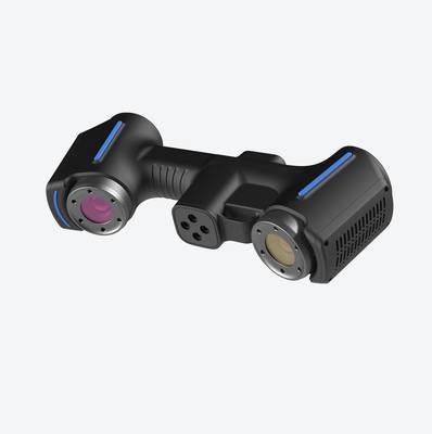
The principle is straightforward. A handheld scanner projects a pattern or laser line onto the part, cameras record the deformed pattern from known angles, and software reconstructs surface coordinates. The result is not a single measurement value. It is a dense digital representation of the part surface that can be compared with nominal geometry.
For semiconductor components, this means the scanner must resolve small sealing faces, bore positions, and thin-wall geometry well enough to support first-article and in-process decisions.
The Workflow That Makes Scanning Inspection-Grade
Raw point data does not automatically produce a dimensional record. The workflow has to be built around four steps: capture, alignment, targeted rescan, and validation.
| Step | What happens | Why it matters |
|---|---|---|
| Capture | Scan the part from multiple orientations to cover datums and critical features. | Missing a datum or sealing face can invalidate the entire alignment. |
| Align | Register the point cloud to the CAD model or a reference coordinate system. | Deviations must be evaluated against the correct GD&T callouts. |
| Targeted rescan | Rescan only thin or noisy regions instead of restarting the job. | Saves time and improves local data quality where tolerance is tight. |
| Validate | Compare measured geometry to tolerance bands and export a deviation map or report. | Creates a repeatable dimensional record for quality and engineering review. |
This sequence matters because a scanner can collect millions of points and still miss the one surface that drives assembly yield. Alignment is the step that turns surface data into inspection data. Without a stable datum plan, repeated scans land in different coordinate systems, and deviation results become unreliable.
Where Scanning Differs from Contact Metrology
Contact metrology and 3D scanning for mechanical components are not direct replacements. They answer different measurement questions.
| Aspect | Contact metrology | 3D scanning for mechanical components |
|---|---|---|
| Data type | Discrete probed points | Dense point cloud and surface deviation map |
| Setup | Custom fixtures and multiple setups for complex parts | Fewer setups, handheld access to difficult areas |
| Coverage | Sparse, predefined paths | Continuous surface coverage across visible areas |
| Best fit | Simple prismatic parts, reference features | Complex geometry, thin walls, freeform surfaces, first-article review |
CMMs still work well for simple prismatic parts and reference features. But complex internal channels, thin walls, and freeform surfaces force long stylus paths, custom fixtures, and repeated setups. Each setup introduces alignment error and produces sparse point data, so engineers never see the full surface. A first-article report may show a few dozen probed points while the rest of the part remains unverified.
Scanning changes the data continuity. It captures the visible surface as a continuous digital record, which supports GD&T evaluation and faster engineering decisions. The trade-off is that scanning is optical. Surface condition, access, and alignment strategy influence the result more than they do with contact probing.
Where the Method Fits—and Where It Does Not
3D scanning for mechanical components delivers the most value when the inspection target has complex geometry or dense dimensional callouts that are slow to cover with contact probing. Semiconductor components often fall into this category because of small sealing faces, tight bore positions, and thin walls.
The method fits well for:
- First-article inspection on parts with complex or freeform surfaces
- In-process checks where setup time must stay low
- Deviation mapping across large surface areas
- Digital record creation for supplier review and engineering collaboration
It is less suitable when:
- The critical feature is a very small bore or deep internal channel that cannot be optically accessed
- The surface is highly reflective or translucent and cannot be prepared
- The tolerance is so tight that contact verification is still required as a reference method
- The part has no stable datum features for repeatable alignment
Scanning should be treated as a complementary metrology tool, not a universal replacement. The decision to use it depends on the feature geometry, surface condition, and the type of dimensional record the quality team needs.
Selection Considerations Before Deployment
Before deploying 3D scanning for mechanical components on a production floor, teams should confirm three things on site.
| Validation item | What to check |
|---|---|
| Surface condition | Reflective, translucent, or dark areas may require matting or different exposure settings. |
| Alignment plan | Use machined datums or stable reference features so repeated scans land in the same coordinate system. |
| Repeatability loop | Capture, align, rescan the same feature, and compare the spread against the print tolerance. |
Surface condition is often underestimated. Reflective surfaces, thin edges, and small bores can produce noisy data. If the surface cannot be prepared, the scan may not be usable for tight tolerance evaluation. The alignment plan is equally important. Without stable datums, repeated scans will not land in the same coordinate system, and deviation results will drift.
The validation loop is the final gate. Capture the part, align it to CAD, rescan a critical feature, and compare the spread against the print tolerance. If the variation stays inside an acceptable band, the approach is ready for production use. If not, the team needs to adjust surface preparation, alignment strategy, or scan settings before relying on the data.
INSVISION AlphaScan in This Workflow
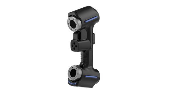
INSVISION AlphaScan fits this context because it is built for dense surface capture on semiconductor components without the same fixture and access constraints as contact metrology. The handheld form factor allows an engineer to scan the part from several orientations, covering critical features and datum areas without building custom fixtures for every setup.
The value of AlphaScan is not the point count alone. It is the ability to move through the capture-align-rescan-validate sequence quickly enough to support first-article and in-process decisions.
When the inspection target includes complex internal channels, thin walls, or freeform surfaces, a handheld scanner such as INSVISION AlphaScan can reduce the number of setups and produce a continuous digital record that quality and engineering can review together.
That record becomes the basis for deviation maps, GD&T evaluation, and supplier discussions. The scanner supports the workflow rather than replacing it. The engineering team still defines the datum plan, validates surface condition, and confirms repeatability on the actual part at the actual station.
Common Misconceptions and Technical Q&A
Does more points mean better accuracy?
Not automatically. A dense point cloud is only useful if the data is aligned to the correct datum structure and the critical features are resolved well enough for the tolerance band. A scanner can collect millions of points and still miss a small sealing face if the capture plan is incomplete.
Can 3D scanning replace a CMM?
In some applications it can reduce the number of contact measurements, but it does not replace contact metrology for every feature. Small deep bores, highly reflective surfaces, or extremely tight tolerances may still require contact verification. Scanning is best understood as a complementary method that provides continuous surface data where contact probing is slow or impractical.
Do reflective surfaces require preparation?
Yes. Reflective or translucent areas change how much light returns to the scanner and can produce noisy data. A matting spray or adjusted exposure settings may be needed before scanning. Validation on the actual part is the only way to know whether the surface condition is acceptable.
Is 3D scanning only for reverse engineering?
No. When scan data is aligned to a CAD reference and evaluated against GD&T callouts, 3D scanning for mechanical components becomes a dimensional inspection tool. The same point cloud can support both reverse engineering and inspection, but the workflow and reporting requirements are different.
Summary
3D scanning for mechanical components becomes a dimensional inspection tool when the workflow is built around capture, alignment, targeted rescan, and validation. For semiconductor components with tight bore positions and thin walls, that sequence matters more than the scanner’s raw point count. INSVISION AlphaScan supports this workflow as a handheld system for dense surface capture and CAD-based deviation analysis.
Before deployment, teams should validate surface condition, datum alignment, and repeatability on the actual part at the actual station. If the validation loop stays within the print tolerance band, scanning can move from reverse engineering into first-article and in-process inspection.
Hangzhou Insvision Technology Co., Ltd.
Address: Building 1, No. 1399 Liangmu Road, Yuhang District, Hangzhou, Zhejiang 311121, China
Copyright © Hangzhou Insvision Technology Co., Ltd. All rights reserved.
Copyright © Hangzhou Insvision Technology Co., Ltd. All rights reserved.