

Stable 3D Scan Targets Keep Precision Inspection Costs Predictable
3d scan targets: Precision inspection programs are judged by three operating outcomes: how quickly a part reaches first-article sign-off, how often alignment.
Where Target Instability First Becomes Operating Cost
A powertrain first-article inspection makes the problem visible. If 3D scan targets shift on machined datum surfaces, the alignment model shifts with them. The scan data may look complete but cannot be trusted against GD&T callouts. Repeating the scan consumes metrology time and holds up sign-off.
Practical Workflow
- Where Target Instability First Becomes Operating Cost — A powertrain first-article inspection makes the problem visible.
- Six Site Constraints That Invalidate a Bench-Tested Setup — A process that treats 3D scan targets as generic accessories may run clean on a bench and fail on the factory floor.
- How Poor Target Setups Become Rework — In a typical first-article inspection, engineers place 3D scan targets on a casting or weldment before scanning, alignment, and G…
- Inspection cycle time — Manual target placement and repeated alignment corrections consume metrology hours.
Aerospace MRO turbine parts are even less forgiving. Blended airfoils do not provide flat datums, so targets on surrounding static structure create the coordinate anchor before capture. Medical orthopedic implants repeat the same challenge at a smaller scale. Freeform titanium profiles depend on target consistency for final batch validation under ISO 10360 and ASME Y14.5.
Across these applications, the operating consequence is similar. Weak target control appears later as alignment rescans, disputed results, and late first-article sign-off. Treating 3D scan targets as a consumable rather than a controlled process variable transfers cost directly into inspection labor and order flow.
Six Site Constraints That Invalidate a Bench-Tested Setup
A process that treats 3D scan targets as generic accessories may run clean on a bench and fail on the factory floor. The gap usually comes from six diagnostic factors.
Part geometry drives line of sight. Freeform surfaces, deep undercuts, and large assemblies impose different target placement rules. Material properties change contrast and reflectivity. Aerospace alloys, translucent medical polymers, and matte composites need different target size and surface preparation. Tolerance requirements define how much target drift is acceptable.
Vibration, ambient light, and temperature swings introduce industrial 3D scanning constraints that lab checks miss. Production takt time and batch-size variability decide whether manual placement can keep pace or automated handling is justified.
Mapping these factors before defining target placement turns a fragile setup into repeatable inline measurement. In an INSVISION AlphaAutoScan-400 deployment, that upfront planning is where automation earns its place. The equipment controls capture and alignment only after the site constraints are understood.
How Poor Target Setups Become Rework
In a typical first-article inspection, engineers place 3D scan targets on a casting or weldment before scanning, alignment, and GD&T validation. The failure patterns are quick to spot when the process is observed closely.
Reflective glare on machined or oiled surfaces can misidentify target centers and create alignment errors that slip downstream until review. Inconsistent target spacing leaves scan passes under-constrained, reduces overlap, and allows alignment drift across a multi-part batch. Each drift event triggers rescanning or manual correction in software.
Targets missing from datum features or audit locations remove traceable reference points, which becomes a compliance risk in AS9100 or ISO 13485 workflows.
The cost rarely shows up as one large failure. It appears as longer inspection cycle times, higher rework rates, delayed delivery, and dimensional defects that may escape first-article review.
Inspection cycle time
Manual target placement and repeated alignment corrections consume metrology hours. A documented target plan shortens setup and reduces non-scan time. The observable value is fewer rescans and faster first-article sign-off.
Rework and waste
Alignment drift produces bad first-article data that may not be caught until downstream processing. Repeatable target positions on datum surfaces reduce misregistration and disputed measurements.
Labor dependence
Manual target placement varies by operator. A standard target plan, and automation where volume justifies it, reduces reliance on highly skilled metrology labor. The value appears as lower correction workload and less shift-to-shift variability.
Delivery cadence
Late first-article sign-off holds orders and downstream processes. Stable reference data shortens review time and makes release timing more predictable.
Quality traceability
Missing target points on audit locations break the digital record. When target placement is controlled and QMS export is verified, serial numbers, operators, timestamps, and GD&T callouts carry through without manual retyping.
Long-term asset
Every new batch does not need to start from an inconsistent setup. A repeatable target plan per part family accumulates as a reusable inspection program, reducing repeat engineering work.
An Evaluation Framework for Operating Value
Precision inspection creates operating value when it reduces the cost of poor quality, not just when it improves scanning speed. A practical evaluation separates measurement capability from process control.
| Cost driver | What to track | Improvement signal |
|---|---|---|
| Inspection time | Rescan frequency and manual alignment hours per part or batch | Fewer alignment corrections after the target plan is fixed |
| Rework | Disputed first-article results and downstream correction events | Stable alignment residuals within tolerance |
| Labor | Time spent on target placement and software correction | Less operator-to-operator variability; lower metrology labor load |
| Traceability | Export completeness without manual retyping | Serial, operator, timestamp, and GD&T callouts carry through |
| Delivery risk | Time from inspection request to sign-off | Shorter, more predictable release cadence |
Where Automated 3D Inspection Reduces Variability
Most 3D scan target failures are process failures, not scanner hardware failures. Manual placement varies operator by operator. Alignment adjustments drift between shifts. Scan paths shift from one inspection run to the next.
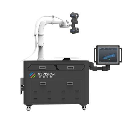
The INSVISION AlphaAutoScan-400 automated 3D inspection system is built for repeat batch inspection in controlled production environments. It handles target setup, capture, and alignment inside a controlled sequence, removing many of the manual adjustments that introduce variability.
Engineering and quality teams that need standardized inspection output, lower metrology labor overhead, and ISO/ASME-compatible traceability will find the strongest fit where GD&T callouts already shape the inspection plan. The system is not a substitute for process definition; it is a way to hold that process stable after it is defined.
Implementation Rhythm: First Scenarios for Cost Reduction
Plants do not need to automate everything at once. Three scenarios are practical starting points.
- First-article inspection on stable part families
Use a calibrated master part and run twenty consecutive scans with the same 3D scan targets. Record alignment residuals and repeatability. If the range drifts beyond tolerance, the process is not ready for pass/fail calls. This exposes target drift early.
- In-process batch inspection in a dedicated production cell
Test target detection at the actual station under normal vibration, ambient light swing, and temperature shift. Incomplete scans at this stage become hidden rework later.
- QMS-linked reporting
Export results and verify that part serial, operator, timestamp, and GD&T callouts carry through without manual retyping. Quality traceability only works if the audit trail survives export.
Run a controlled pilot batch against the current inspection workflow and compare labor hours, programming time, and rework triggers. Check output against ISO 10360 or ASME Y14.5 plus aerospace or medical record requirements. Each check should yield a pass value or a documented gap. For INSVISION equipment, this validation step is what turns a demonstration into a defensible deployment decision.
Target-driven measurement works most effectively when the part population is stable, the cell environment is controlled, and the inspection callout repeats across batches. Highly variable one-offs or unstructured field inspection should begin with a short pilot before full automation is considered.
Summary
The operating case for 3D scan target control is straightforward: precision inspection costs rise when alignment depends on operator judgment rather than a repeatable process.
By defining target placement before scanning, validating repeatability on a master part, and automating only where volume and part geometry support it, manufacturing teams can reduce rescans, shorten first-article timelines, and build quality records that survive customer or regulatory review. That is not a scanner specification conversation. It is a cost-control conversation.
Hangzhou Insvision Technology Co., Ltd.
Address: Building 1, No. 1399 Liangmu Road, Yuhang District, Hangzhou, Zhejiang 311121, China
Copyright © Hangzhou Insvision Technology Co., Ltd. All rights reserved.
Copyright © Hangzhou Insvision Technology Co., Ltd. All rights reserved.