

A Practical Validation Framework for 3D Measuring Machines in Existing Quality Workflows
3d measuring machine: Most aerospace MRO quality teams do not begin an inspection equipment evaluation with scanner specifications.
Where deployment gaps appear before scanning starts
A 3D measuring machine that cannot relate scan data to ASME Y14.5 datum references, or cannot export results into an existing QMS, adds manual rework before any useful dimensional comparison begins. In aerospace MRO, that manual step is not trivial.
Turbine components and casing repairs arrive with inspection histories that must connect to current findings, and a scan file that cannot enter the approval trail becomes an isolated dataset.
Key Points at a Glance
- A 3D measuring machine that cannot relate scan data to ASME Y14.5 datum references, or cannot export results into an existing QMS, adds manual r…
- How does a quality team know a 3D measuring machine will handle production parts rather than clean demonstration samples?
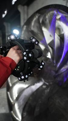
- Integrating a V-Track tracking 3D scanning system into an existing workflow starts with mapping where dimensional data is actually consumed.
- During delivery, INSVISION configures the V-Track tracking 3D scanning system around the factory’s existing quality workflow rather than the oth…
Geometric fit creates a second failure point. Large turbine casings, automotive body assembly subassemblies, and energy-sector wind turbine parts often sit outside the comfortable field of view and standoff range of general-purpose scanning setups. Coverage becomes inconsistent, or targeting consumes too much time.
The part may not need a dedicated lab, but the scanner still has to handle the actual envelope, surface finish, and fixture position.
Operator readiness is another route to underuse. Teams that receive software training alone may never validate measurement routines against ISO 10360 artifacts. The system remains unproven against the tolerances the plant actually reports, and production staff may stop trusting the output after the first unresolved deviation.
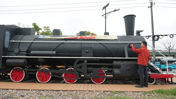
INSVISION treats these as delivery problems rather than scanner specification problems. The first step is a review of part geometry, GD&T requirements, and QMS export constraints. Only then is a V-Track tracking 3D scanning system specified around the actual inspection task. That sequence is what makes a 3D measuring machine repeatable for aerospace MRO or a 3D measurement system useful in automotive quality control.
Validation on representative parts, not only lab demos
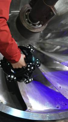
How does a quality team know a 3D measuring machine will handle production parts rather than clean demonstration samples? INSVISION builds a validation phase into delivery for that purpose. Application engineers work with production and quality staff to select representative parts that span dull and polished surfaces, small and large envelope sizes, tight GD&T callouts, and looser form checks.
The V-Track tracking 3D scanning system is then run either in a laboratory or directly on the factory floor. Ambient vibration, lighting shifts, awkward part positioning, and fixture constraints remain part of the test because they will be part of daily use.
| Validation variable | Why it matters | Field observation |
|---|---|---|
| Surface finish range | Shiny and dull areas reflect differently and stress exposure settings | Scan data remains complete across material transitions |
| Envelope size range | Large assemblies strain field of view and standoff distance | Coverage stays consistent without excessive target changes |
| Tolerance mix | Tight GD&T callouts and broad form checks require different reporting thresholds | Deviation results correspond to CMM or gauge references where those exist |
| Site conditions | Floor vibration, fixture limitations, and lighting changes affect repeatability | Multiple scan passes remain stable enough for the intended inspection decision |
Where the site already uses CMM or gauge results, scan data gets cross-checked against those references. The goal is qualitative confirmation that the scan output fits its intended inspection use. INSVISION does not create performance metrics during validation. The phase ends with formal solution confirmation, where the quality team signs off that the system meets core inspection requirements.
Workflow integration at existing quality gates
Integrating a V-Track tracking 3D scanning system into an existing workflow starts with mapping where dimensional data is actually consumed. Most plants already have gates at post-machining, post-assembly, and first-article inspection. The implementation team does not replace those gates; it places the scanner at the gate where surface data reduces the most rework.
For a high-mix aerospace MRO cell, that often means a mobile workstation near the assembly bay rather than a dedicated measurement lab. Site preparation focuses on a stable floor area and clear line of sight for the tracking cameras, not reinforced foundations or special enclosures.
Because the V-Track system scans large assemblies without repositioning the part, operators avoid unsafe lifting and awkward fixture setup, an ergonomic point that aligns with North American and European workplace safety expectations.
Each scan job is defined against a production milestone. The resulting GD&T report feeds into the existing nonconformance or first-article documentation trail. Disruption stays low because the 3D measuring machine becomes an inspection step inside the current process, not a separate quality project.
Data output and reporting alignment
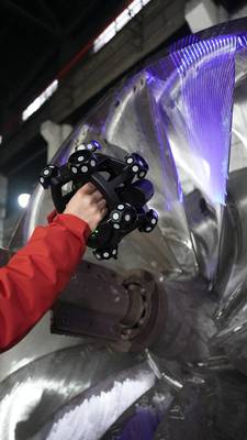
During delivery, INSVISION configures the V-Track tracking 3D scanning system around the factory’s existing quality workflow rather than the other way around. Scan data can be exported directly into standard CAD comparison, GD&T analysis, and first-article inspection reports aligned with ISO and ASME requirements.
That alignment matters in facilities where FAI documentation must match established review cycles without extra interpretation.
INSVISION builds report templates to mirror the customer’s current document formats, so quality engineers do not re-enter measurements or reformat scan outputs by hand. Where a plant already uses a QMS or an Industry 4.0 data pipeline, the 3D measuring machine output is configured to feed those systems in common file formats for traceability and continuous improvement analysis.
The practical result is a measurement tool that drops into existing software and reporting routines, avoiding a costly new software stack or a full workflow overhaul.
Role-based training and post-implementation review
Training follows the roles that will use the system. Shop floor quality technicians receive hands-on operation training covering setup, scan paths, and first-line checks. Quality engineers attend advanced sessions on data analysis and report customization. Procurement and operations leadership receive an overview focused on value tracking and future deployment planning.
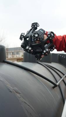
After training, the INSVISION application team runs a post-implementation review with the customer. They compare system performance against the original validation goals and adjust workflows or training where needed. This keeps the 3D measuring machine aligned with production realities as parts, fixtures, and reporting requirements change.
Reusable scenarios across industries
The delivery framework transfers beyond aerospace MRO. It applies to automotive tier 1 assembly quality control, energy sector large component measurement, and medical device large assembly verification. Teams can assess fit by checking three factors: part size range, required tolerance levels, and deployment environment, whether laboratory, shop floor, or mobile.
A structured validation and delivery approach helps a 3D measuring machine deliver consistent, sustainable value where parts are large, the workflow is regulated, and the data must feed an existing quality record.
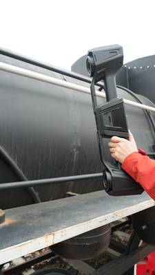
Structured delivery is the difference between owning scanning hardware and having a measurement process that quality engineers trust. For plants that inspect large mixed-surface components, maintain tight GD&T callouts, and operate established QMS gates, a validation-first deployment of the V-Track tracking 3D scanning system reduces the risk that new equipment becomes an isolated lab tool.
It becomes an inspection step within the workflow the plant already runs.
Hangzhou Insvision Technology Co., Ltd.
Address: Building 1, No. 1399 Liangmu Road, Yuhang District, Hangzhou, Zhejiang 311121, China
Copyright © Hangzhou Insvision Technology Co., Ltd. All rights reserved.
Copyright © Hangzhou Insvision Technology Co., Ltd. All rights reserved.