

Large-Format 3D Scanning in Heavy Manufacturing: A Practical Workflow with the INSVISION AlphaVista
When a cast iron turbine housing comes off the machining line and the inspection team needs to capture every bolt hole position, flange flatness, and wall thick
The Real-World Challenge of Large-Scale Part Inspection
A typical heavy manufacturing site handles components that often exceed two meters in length and feature complex cast or forged geometries. Technical managers in quality and production face several recurring difficulties. First, the sheer size of the parts means that fixed CMMs require multiple setups and extended probe cycles, often taking a full shift to measure a single unit.
Second, critical surfaces are frequently deep inside cavities or hidden behind flanges, making them inaccessible to line-of-sight optical trackers. Third, the shop floor environment itself—vibration, temperature swings, airborne dust—introduces measurement noise that traditional instruments struggle to filter out.
The result is a trade-off: either accept a lower sampling density and risk missing local deviations, or invest hours in moving and stabilizing the part for a full inspection. Neither option fits a modern production schedule that demands in-process feedback and reduced lead time.
Deployment Validation Checklist
| Focus Area | Decision Point | Deployment Note |
|---|---|---|
| Target part | Check size, surface condition, and key tolerances against the scan task | Run a full trial scan on a representative part |
| Data workflow | Verify point cloud, deviation map, and quality-report handoff | Confirm export formats and review ownership in advance |
| Shop-floor use | Review training, calibration, lighting, and working space | Keep the validation record as a repeatable inspection reference |
Key Points at a Glance
- A typical heavy manufacturing site handles components that often exceed two meters in length and feature complex cast or forged geometries.
- INSVISION designed the AlphaVista large-format handheld 3D scanner specifically for this category of work.
- In practice, deploying the AlphaVista on a large casting or weldment follows a straightforward sequence that can be completed by a single operat…
- Plants that adopt this method for large-part inspection report several qualitative shifts in their daily operations.
These challenges create a clear need for a measurement approach that handles large volumes quickly, operates reliably on the shop floor, and delivers dense point cloud data suitable for both dimensional inspection and downstream reverse engineering. Handheld 3D scanning is the natural candidate, but only if the scanner can maintain metrology-grade consistency over wide fields of view and long scanning sessions.
How the AlphaVista Approach Matches the Task
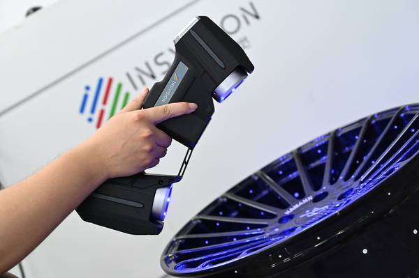
INSVISION designed the AlphaVista large-format handheld 3D scanner specifically for this category of work. The device uses a multi-line blue laser array combined with an integrated 3D scan engine that processes incoming data streams in real time.
Rather than capturing the part in narrow strips and stitching them later, the wide field of view—supported by the scanner’s extended standoff and large capture area—allows an operator to cover broad surfaces in fewer passes. This is a direct response to the primary pain point of large-part metrology: the cumulative time spent walking back and forth and repositioning a smaller scanner.
The optical architecture is built around blue laser light, which maintains better fringe contrast on shiny or partially oxidized metal surfaces than red laser alternatives. This matters in foundry and machining environments where parts have not yet been painted or fully cleaned.
The scanner’s 3D scan engine constantly monitors frame-by-frame data quality, automatically adjusting exposure and filtering out outliers caused by ambient light fluctuations. The result is a consistent point density even when moving from flat reference planes to deep recesses.
The accompanying INSVISION 3D software platform then handles the scan-to-CAD alignment, dimension extraction, and report generation in a single workspace, so the inspection team does not need to export data to multiple third-party tools.
A Walkthrough of the On-Site Workflow
In practice, deploying the AlphaVista on a large casting or weldment follows a straightforward sequence that can be completed by a single operator. First, the part is prepared with a sparse set of reference targets, either adhesive markers or magnetic mounts, placed at key locations on the surface and around the periphery.
The scanner’s tracking system continuously references these targets to build a global coordinate frame that stays stable even as the operator moves around the part.
The scanning phase itself is the most visible departure from traditional methods. The operator walks the scanner across the part at a steady pace, holding it at a distance that keeps the entire area of interest within the laser projection field. The large capture volume means that even long, sweeping passes capture the full width of a flange or the surface of a manifold without missing edges.
For deep pockets or narrow internal passages, the scanner switches to a single-line deep-hole mode, allowing the laser to reach areas that a CMM probe would struggle to access. Throughout the scan, the 3D scan engine tracks the scanner’s position relative to the part and registers the incoming point cloud frames in real time.
The live preview on the connected computer shows the growing surface model, giving the operator immediate visual confirmation that no gaps remain.
Data processing follows directly within the INSVISION software. The platform aligns the captured point cloud to the nominal CAD model, calculates a color map of surface deviations, and generates dimension reports for pre-defined GD&T callouts.
Because the scan engine output is a dense, registered mesh, the same data set can be used for root cause analysis of machining drift or for generating a reverse-engineered CAD model when the original drawings are missing. The full workflow, from first scan to final report, often completes in a fraction of the time required by a CMM-based inspection on the same part.
Observable Impact and Broader Industrial Relevance
Plants that adopt this method for large-part inspection report several qualitative shifts in their daily operations. The measurement cycle time drops noticeably, which allows quality teams to inspect a higher percentage of production units instead of checking only a sample. The dense point cloud reveals geometric deviations that would be missed by touch-probe strategies limited to a few dozen points per feature.
Feedback reaches the machining cell faster, so tool offsets can be adjusted before the next part is cut. In addition, the digital twin generated during the scan becomes a reusable asset for engineering analysis, tooling design, and long-term wear monitoring of patterns and dies.
The same approach extends naturally to other large-format applications: wind turbine hubs, marine propellers, railcar bogie frames, and large composite tooling. In each case, the combination of a wide capture area, blue laser performance in industrial lighting, and a unified software platform removes the bottlenecks that previously made full-shape 3D scanning impractical on the production floor.
The INSVISION AlphaVista, built around a responsive 3D scan engine, provides a practical bridge between the precision of lab metrology and the speed and resilience demanded by real manufacturing environments.
Hangzhou Insvision Technology Co., Ltd.
Address: Building 1, No. 1399 Liangmu Road, Yuhang District, Hangzhou, Zhejiang 311121, China
Copyright © Hangzhou Insvision Technology Co., Ltd. All rights reserved.
Copyright © Hangzhou Insvision Technology Co., Ltd. All rights reserved.