

How a 3D Measuring Tool Cuts Rework and Improves Factory Efficiency
## The Hidden Costs of Traditional Measurement and Inspection Production managers know that inspection isn’t where value is created — it’s where value is verifi
The Hidden Costs of Traditional Measurement and Inspection
Production managers know that inspection isn’t where value is created — it’s where value is verified. When that verification process drags on, ties up skilled labor, or generates data that’s too sparse to act on, the knock-on effects ripple through delivery schedules, rework loops, and customer confidence. Traditional measurement workflows often rely on hand tools, CMMs, or single-point laser trackers.
Each requires significant setup time, a controlled environment, and operators who understand both the part and the metrology method. In high-mix or large-part production, the most expensive outcome isn’t a single bad measurement; it’s the cumulative cost of waiting for inspection, moving parts to a metrology lab, and repeating work because the first-pass data wasn’t comprehensive enough to spot a deviation early.
Selection Dimensions and Field Checks
| Focus Area | Decision Point | Deployment Note |
|---|---|---|
| The Hidden Costs of Traditional Measurement and Inspect… | Production managers know that inspection isn’t where value is created — it’s where value is verified. | When that verification process drags on, ties up skilled labor, or generates data that’s too sparse to act on, the knock-on effects ripple throu… |
| Where 3D Scanning Shifts the Cost Equation | A tracking-based 3D measuring tool like the INSVISION V-Track system changes the inspection workflow at three critical points. | First, it eliminates the need to move large or heavy parts to a dedicated measurement room. |
| Building a Simple Cost-Justification Framework | Rather than reaching for a generic ROI percentage, a more convincing approach for leadership is to map the current-state costs of the inspection func… | The framework can be built around four line items. |
| First Steps to Deploy a 3D Measuring Tool on Your Floor | The most practical way to start is to pick one or two part families where the current inspection time is a known pain point and the geometry is large… | A typical first application is a large weldment or casting that currently requires a CMM and multiple setups. |
These costs show up in overtime hours, expedited shipping, and scrap that could have been avoided. They also appear in less visible places: the time engineers spend interpreting incomplete reports, the risk of passing a near-limits feature that later fails in assembly, and the slow erosion of on-time delivery records. For many factories, the inspection bottleneck is accepted as a fixed constraint.
A closer look usually reveals that the constraint is built on tooling, handling, and data density — all areas where a modern 3D measuring tool can fundamentally change the arithmetic.
Where 3D Scanning Shifts the Cost Equation
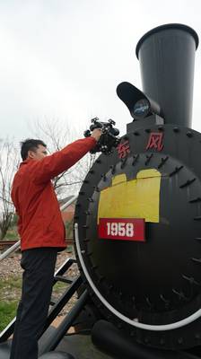
A tracking-based 3D measuring tool like the INSVISION V-Track system changes the inspection workflow at three critical points. First, it eliminates the need to move large or heavy parts to a dedicated measurement room. The optical tracking unit stays on the shop floor, and the handheld scanner moves around the part, capturing full-field data without repositioning the workpiece.
This alone can cut hours of crane time and fixture setup from a single inspection cycle. Second, the data density is orders of magnitude higher than what a point-by-point measurement produces. Instead of a few dozen probed locations, the operator gets a dense point cloud or mesh that reveals surface deviations, twist, and feature relationships across the entire geometry.
Problems that would have been invisible in a sparse report become obvious, often before the part leaves the fixture.
Third, the software pipeline that accompanies the V-Track system — feeding scan data directly into INSVISION’s 3D inspection and alignment tools — compresses the time from measurement to actionable report. Deviations are mapped onto a color plot against the CAD model, GD&T callouts are evaluated, and the result is a shareable digital record that supports both immediate pass-fail decisions and long-term trend analysis.
For a production manager, the value isn’t just in faster inspection; it’s in the ability to run more frequent checks without adding headcount. That tighter sampling cadence catches drift early, reducing the batch size of potentially non-conforming parts and keeping rework costs contained.
Building a Simple Cost-Justification Framework
Rather than reaching for a generic ROI percentage, a more convincing approach for leadership is to map the current-state costs of the inspection function and then estimate how those costs shift under a 3D scanning workflow. The framework can be built around four line items.
The first is labor hours: how many operator and engineer hours per month are spent on inspection setup, part handling, data interpretation, and rework documentation? The second is turnaround time: what is the average lag between a part being ready for inspection and a completed report reaching the decision-maker?
The third is rework and scrap: what is the current monthly cost of material and labor consumed by rework that originated from measurement gaps or late detection? The fourth is opportunity cost: what orders are delayed, and what additional inspection capacity would be needed to support a new contract or a shorter delivery promise?
With these baselines, a trial deployment of a tracking 3D scanner can be evaluated against observed changes in labor hours, throughput, and rework incidents. Even without hard numbers upfront, the operational pattern is clear: a system that captures full-field data in a single setup, reduces part handling, and feeds a digital inspection pipeline tends to compress the entire inspection cycle and make it more repeatable.
The financial implication is a reduction in the variable cost of quality, which directly improves margin on every unit shipped.
First Steps to Deploy a 3D Measuring Tool on Your Floor
The most practical way to start is to pick one or two part families where the current inspection time is a known pain point and the geometry is large enough to make repositioning expensive. A typical first application is a large weldment or casting that currently requires a CMM and multiple setups.
With the V-Track system, the operator scans the part in the fabrication area, the software aligns the data to the CAD model through optical tracking, and the first report is generated before the part would have even reached the metrology lab. The second application is often a recurring in-process inspection on a machining line, where the goal is to catch tool wear or fixture shift before the next part is machined.
By scanning a part while it’s still on the machine or on a nearby staging table, the team can make a keep-or-adjust decision in minutes.
A third scenario worth exploring is supplier quality or incoming inspection. Instead of relying on a supplier’s dimensional report, the receiving team can scan a first-article or a sample from a new batch and compare it directly to the CAD model. This builds a digital traceability record that is far more complete than a handwritten checklist.
Across all three scenarios, the common thread is that the measurement tool moves to the part, not the other way around. That shift in logistical logic often delivers the most immediate operational savings, and it sets the foundation for a broader digital quality strategy that grows with the business.
Hangzhou Insvision Technology Co., Ltd.
Address: Building 1, No. 1399 Liangmu Road, Yuhang District, Hangzhou, Zhejiang 311121, China
Copyright © Hangzhou Insvision Technology Co., Ltd. All rights reserved.
Copyright © Hangzhou Insvision Technology Co., Ltd. All rights reserved.