

From Scan Data to Inspection Reports: 3D scan tool for mouldigs to get the knife in Practice
3d scan tool for mouldigs to get the knife shape: Moulding Tool Knife Edge Measurement: Persistent Industrial Challenges Moulding Tool Knife Edge.
Moulding Tool Knife Edge Measurement: Persistent Industrial Challenges
For production teams running wood, plastic, or composite moulding lines, the knife edge profile on a moulding tool is the single most important geometry in the process. Yet most plants still measure these edges the way they did twenty years ago. Calipers give you a thickness reading at one point. An optical comparator shows a shadow, but only for simple profiles.
A coordinate measuring machine can capture points, but struggles with continuous curved cutting edges and tight radii.
Capability and Deployment Mapping
| Focus Area | Decision Point | Deployment Note |
|---|---|---|
| Moulding Tool Knife Edge Measurement: Persistent Indust… | For production teams running wood, plastic, or composite moulding lines, the knife edge profile on a moulding tool is the single most important geome… | Yet most plants still measure these edges the way they did twenty years ago. |
| Step-by-Step Workflow for INSVISION 3D Scanning of Moul… | The core value of a 3D scan tool for mouldings to get the knife shape is not just capturing points on a blade. | It is the removal of ambiguity from the measurement loop. |
| CAD-Native Output: A Core Engineering Advantage for Mou… | Moulding teams have watched CAD-native inspection move from a nice-to-have to a standard deliverable on new tooling programs. | The reason is straightforward: when quality data arrives in a proprietary format, engineering loses hours converting files, re-aligning coordina… |
| Validating Moulding Knife Shape Data for Operational Pe… | The shift from manual profile tracing to a 3D scan tool for mouldings to get the knife shape has changed how tooling teams approach incoming inspecti… | Where a comparator or hand gauge once gave a single cross-section, scanning now produces a dense point cloud that can be compared against nomina… |
The result is predictable. Different inspectors get different results on the same tool. Shift-to-shift variation creeps into first-article checks. When a new knife set arrives from the grinder, validation drags on while production waits. And when a tool wears in service, there is rarely a reliable digital record of what the edge looked like when it was new. Without that baseline, wear tracking becomes guesswork.
This is exactly where a 3D scan tool for mouldings to get the knife shape changes the conversation. Instead of sampling a few points, a scanner captures the full edge profile as a dense point cloud. That data can be compared directly against nominal CAD geometry, archived for later wear analysis, or sent back to the grinding supplier as a measurable acceptance record.
For teams working under ISO 1101 or ASME Y14.5 tolerancing requirements, it closes a persistent documentation gap without slowing the inspection workflow.
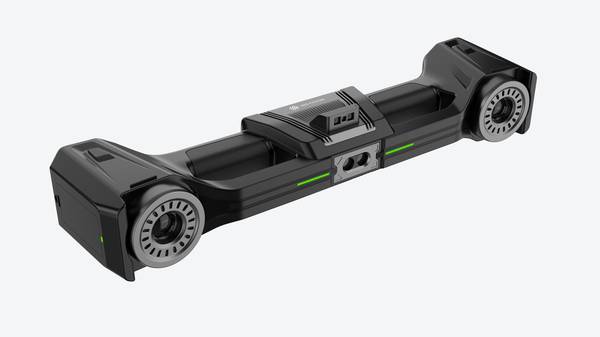
Step-by-Step Workflow for INSVISION 3D Scanning of Moulding Knife Shapes
The core value of a 3D scan tool for mouldings to get the knife shape is not just capturing points on a blade. It is the removal of ambiguity from the measurement loop. Process engineers and quality managers do not need another dataset that requires hours of manual interpretation. They need a repeatable path from setup to extracted edge geometry.
The INSVISION workflow delivers that by reducing the number of decisions an operator makes at the scanner.
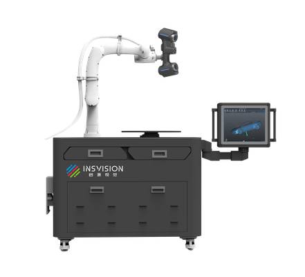
Pre-scan preparation is intentionally light. Moulding knife edges do not require heavy cleaning or contrast spraying in most shop environments. The scanner captures the sharp edge directly from the machined surface. No complex fixturing is required. The tool can rest on a standard inspection table or remain in a holding fixture. This matters in lean manufacturing terms because setup time is non-value-added.
Every minute spent aligning a mould tool on a granite plate is a minute not spent measuring. The non-contact approach also protects the knife edge from the wear and deflection that contact probes can introduce, which is a common concern when checking thin trim blades or precision mould lips.
Scan execution follows a sequential pass along the edge. The scanner captures full knife edge geometry without touching the surface. This works for small precision moulds as well as large trim tools. For a short moulding insert, the operator may complete the pass in one continuous motion. For a long trim blade, the scan can be broken into overlapping sections.
The point is that the full edge profile is acquired without repositioning the mould tool multiple times. That reduces the chance of alignment error between separate setup orientations. The output is a dense point cloud that represents the actual edge condition, not a sparse set of probed points.
Data alignment is where the workflow becomes repeatable. The software aligns the scan to existing reference features or a defined coordinate system. If the mould tool has a known datum structure, the operator can use those same features for alignment. This is important for quality managers who need to compare a scanned knife edge back to the original CAD profile or to a master tool.
Alignment is automatic, not a manual best-fit guess. The result is consistent measurement from one shift to the next, even when different operators run the scan. That consistency is what makes the data usable for first-article inspection or tool wear trending.
Knife shape extraction is the step that separates a general 3D scan from a targeted inspection deliverable. Rather than handing a quality engineer a full mesh and asking them to find the edge, the software isolates the sharp edge profile from the surrounding mould scan data. The operator can then analyze the edge against nominal geometry.
This is useful when checking relief angles, land widths, or localized wear along a trim blade. It also supports reverse engineering when the original knife drawing is missing or outdated. The extracted profile becomes the basis for a replacement blade or a corrective grind.
From a lean manufacturing perspective, this workflow removes manual touch time. The traditional method of tracing a knife edge with a comparator or taking multiple contact measurements is slow and operator-dependent. The INSVISION scan workflow compresses that into a few steps: place the tool, scan, align, extract.
Human error in dimensional measurement is reduced because the operator is no longer deciding where to probe or how to hold a template. The scan captures the edge as it exists. The software handles the interpretation. That is the difference between measuring a few points and measuring the edge.
One practical note for process engineers: this approach works best when the scan strategy is defined once and then reused. The first time a mould tool is scanned, the engineer sets the alignment references and the extraction region. After that, the workflow can be called up for repeat inspections. This is how the method supports production-level use, not just occasional troubleshooting.
It also fits with Industry 4.0 expectations because the scan data can be stored and trended over time to predict knife wear before it causes a moulding defect.
CAD-Native Output: A Core Engineering Advantage for Moulding Teams
Moulding teams have watched CAD-native inspection move from a nice-to-have to a standard deliverable on new tooling programs. The reason is straightforward: when quality data arrives in a proprietary format, engineering loses hours converting files, re-aligning coordinate systems, or rebuilding knife shape geometry before any actual mould work begins. INSVISION 3D scan tools remove that handoff friction.
Scanned knife profiles export directly as STL, PLY, or text-based point cloud files that drop into existing CAD/CAM and mould design platforms without manual rework. For a moulding engineer, this means overlaying captured knife shape data against nominal CAD in seconds to spot wear, chipping, or deviation from design intent.
The same export path supports reverse engineering of legacy tools and first-article inspection reporting without re-authoring scan data. Teams running digital twin or tool lifecycle management systems can feed scanned geometry straight into those databases, keeping quality records and engineering models on a single revision path. That continuity matters more than the scanner’s raw speed.
Validating Moulding Knife Shape Data for Operational Performance
The shift from manual profile tracing to a 3D scan tool for mouldings to get the knife shape has changed how tooling teams approach incoming inspection and rework validation. Where a comparator or hand gauge once gave a single cross-section, scanning now produces a dense point cloud that can be compared against nominal CAD across the full edge length.
The practical question is no longer whether scanning works, but how to turn that scan data into a defensible pass/fail decision.
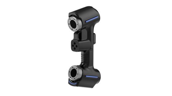
Moulding knife shape validation starts with the same GD&T callouts used for machined components, but the tolerances sit on a thin, often curved cutting edge. ASME Y14.5 profile tolerances apply well here. A unilateral profile zone of a few thousandths of an inch can separate a knife that cuts cleanly from one that tears fibre or leaves witness marks.
The scan-to-CAD colour map makes those deviations visible immediately, but the inspector still needs to confirm the datum alignment matches the tool drawing before accepting the result. That alignment step matters more than the scanner resolution in many cases.
For INSVISION industrial 3D scanner users, the workflow typically follows a fixed sequence. The knife is fixtured or placed on a stable surface, scanned from multiple orientations, and the resulting mesh is registered to nominal CAD in inspection software. The operator reviews the datum structure, checks the profile deviation band against the drawing, and exports a report.
Because output formats include STL, PLY, and TXT, the raw scan can move into most metrology or reverse-engineering packages without a proprietary viewer.
Operationally, three outcomes show up consistently. First, measurement variability between inspectors drops because the scan captures the full edge rather than a handful of discrete check points. Second, mould rework validation turns around faster; a re-ground knife can be scanned and compared to the previous condition record in the time it takes to set up a surface plate and height gauge.
Third, the scan file itself becomes a digital condition record. Over successive sharpenings, the team can track edge retreat, local wear, and distortion trends. That record supports predictive maintenance scheduling instead of waiting for a knife to fail on press.
One point worth noting for Western manufacturing teams: the same scan workflow works in a quality lab and at the press. The data does not care where it was captured, as long as the alignment and reporting settings stay consistent. That consistency is what makes GD&T for mould tool edges practical across a plant rather than confined to a single CMM operator.
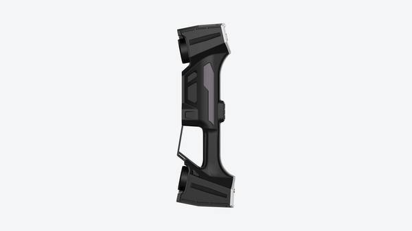
Extended Moulding Industry Use Cases for 3D Knife Shape Capture
New mould tool first-article inspection is where a 3D scan tool for mouldings to get the knife shape earns its keep early. Before full production launch, teams verify that the machined knife edge matches the intended CAD geometry. Traditional touch probing struggles here because the edge is thin, often under a millimeter, and contact pressure can deflect or damage it.
Non-contact scanning captures the full edge profile without loading the surface, giving quality engineers a dense point cloud to compare against nominal GD&T callouts. In-service mould maintenance follows a similar logic. Over repeated cycles, knife edges wear unevenly depending on material fill, gate location, and clamping force.
Periodic scanning tracks wear progression so regrinding can be scheduled before part flash or dimensional drift appears. For legacy mould reverse engineering, many tools still in service lack original CAD data. Scanning the knife shape and adjacent parting surfaces lets teams rebuild a parametric model for spare tooling or design revision.
Parting line verification ties these workflows together: the scan must capture both halves in alignment, confirming that the knife edge profile and the parting line match within tolerance. Automotive interior trim moulding, medical silicone moulding, aerospace composite tooling, and consumer goods injection moulding all face these same edge geometry challenges, though material and cycle conditions vary.
INSVISION scanning platforms output standard formats such as STL, PLY, and TXT, which simplifies handoff to downstream metrology and reverse engineering workflows.
Hangzhou Insvision Technology Co., Ltd.
Address: Building 1, No. 1399 Liangmu Road, Yuhang District, Hangzhou, Zhejiang 311121, China
Copyright © Hangzhou Insvision Technology Co., Ltd. All rights reserved.
Copyright © Hangzhou Insvision Technology Co., Ltd. All rights reserved.