

How 3D Inspection Machine Types Fit Different Factory Inspection Workflows
3d inspection machine: Core 3D Inspection Task Categories in Discrete Manufacturing Core 3D Inspection Task Categories in Discrete Manufacturing The most.
Core 3D Inspection Task Categories in Discrete Manufacturing
The most important decision in 3D inspection is not which scanner to buy, but which task class you are actually trying to solve. Across Western discrete manufacturing, four task profiles dominate: first-article inspection for custom or low-volume parts, in-process quality control on assembly lines, dimensional validation of large structures, and high-batch repeatable component verification.
Each carries different requirements for accuracy, speed, field mobility, and data handling. A system optimized for FAI on a machined aerospace bracket will struggle when pulled onto a renewable energy weldment line. The lean manufacturing implication is direct: matching the 3D inspection machine configuration to the task profile eliminates rework loops and inspection bottlenecks. Standards matter here too.
ISO 10360 governs acceptance and reverification testing for coordinate measuring systems, while ASME Y14.5 defines how GD&T callouts such as profile, position, and runout tolerances must be interpreted from the scan data. Engineering teams evaluating INSVISION industrial 3D scanners should start from the part size, site constraints, marker conditions, takt time, and batch repeatability before comparing specifications.
Deployment Validation Checklist
| Focus Area | Decision Point | Deployment Note |
|---|---|---|
| Target part | Check size, surface condition, and key tolerances against the scan task | Run a full trial scan on a representative part |
| Data workflow | Verify point cloud, deviation map, and quality-report handoff | Confirm export formats and review ownership in advance |
| Shop-floor use | Review training, calibration, lighting, and working space | Keep the validation record as a repeatable inspection reference |
Key Points at a Glance
- The most important decision in 3D inspection is not which scanner to buy, but which task class you are actually trying to solve.
- In pre-sales conversations, the most useful question is rarely “how accurate is the scanner?” It’s usually “what are you actually trying to hold…
- Which configuration actually fits your inspection task?
- Most teams assume a 3D inspection machine is ready for production once the vendor demo looks clean.
Key Constraints That Define 3D Inspection Machine Suitability
In pre-sales conversations, the most useful question is rarely “how accurate is the scanner?” It’s usually “what are you actually trying to hold, and where?” A 3D inspection machine that works well in one cell can be completely wrong for another, not because the hardware is bad, but because the constraint profile doesn’t match.
Part size and tolerance stack is the first filter. A shop checking submillimeter features on machined medical components needs a different optical setup than a team verifying hole patterns across a composite wing skin. Tight GD&T callouts on small parts push toward high-resolution, short-standoff measurement.
Large aerospace or energy components pull the opposite direction: long working distance, wider field coverage, and tolerance bands that may be looser in absolute terms but harder to verify over several meters. Buyers should map the smallest feature they need to resolve and the largest envelope they need to cover before comparing systems. A machine optimized for one end of that range will underperform at the other.
Site access changes the conversation again. A fixed production cell can support a dedicated station with controlled lighting, stable fixturing, and repeatable part presentation. Field MRO work rarely offers any of that. Teams inspecting rotor bores, weld repairs, or airframe sections in a hangar need equipment that can be moved, set up on uneven surfaces, and operated by technicians who are not full-time metrology staff.
INSVISION systems used in these environments tend to be selected for portability and tolerance to shop-floor conditions rather than raw laboratory precision. The right machine for a clean room is not automatically the right machine for a repair depot.
Marker application feasibility is a constraint that gets underestimated. Many 3D inspection workflows rely on adhesive or magnetic targets to help the system track part geometry during scanning. On painted steel structures or machined aluminum, that’s usually fine. On polished turbine blades, silicone molds, or Class A surfaces, markers can contaminate the part or leave residue that violates customer requirements.
Some parts simply cannot be marked. In those cases, the machine must support marker-free alignment or use alternative reference strategies. Buyers should test this early with real production parts, not demo coupons.
Takt time separates inline inspection from offline analysis. A high-speed line checking stamped brackets may allow only seconds per part. A low-volume aerospace cell may allow forty minutes for a first-article layout. The same 3D inspection machine cannot serve both without trade-offs. High-speed checks usually mean reduced point density, automated triggering, and pass-fail logic tied to a few critical dimensions.
Offline work favors dense scans, full surface deviation maps, and interactive review. Mismatching speed to the application creates either a bottleneck or an underused asset.
Batch repeatability is the final filter. High-volume standardized parts reward automation, fixed recipes, and minimal operator decisions. Custom one-off builds reward flexibility, quick setup changes, and software that handles varied geometry without reprogramming.
INSVISION deployments tend to split along this line: repetitive production benefits from locked inspection routines, while job-shop work benefits from fast part-to-part changeover. A machine purchased for repeatability may frustrate a custom fabricator, and a flexible system may feel slow in a high-volume plant.
When these five constraints are evaluated together, the selection path narrows quickly. The goal is not to find the most advanced 3D inspection machine. It’s to find the one whose operating envelope matches the parts, the site, the surface condition, the cycle time, and the production mix.
Miss any one of those, and the result is usually the same: inconsistent data, extra manual work, and capital equipment that sits idle more than it should.
3D Inspection Machine Configurations and Their Ideal Use Cases
Which configuration actually fits your inspection task? The answer depends less on the equipment catalog and more on how the part moves, where the surface sits, and how tight the tolerance stack really is. A handheld scanner that works beside an aircraft wing during overnight MRO will not survive the takt time of a high-batch automotive line.
Nor will a fixed automated cell make sense for validating a wind turbine root section in the field. The practical path is to map the four main 3D inspection machine configurations to the constraints you already know: part size, site freedom, marker conditions, batch repeatability, and the data deliverable your quality system expects.
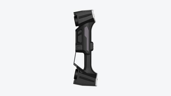
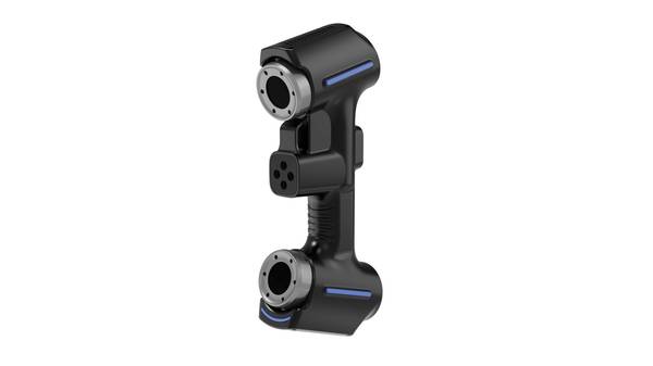
Portable handheld units fit on-site aerospace MRO inspection and large-casting repair where the part cannot move. Operators need freehand access around damaged zones, often with mixed surface finishes and no controlled lighting. The tradeoff is repeatability: handheld results depend more on operator path discipline and scan overlap.
These systems work when the goal is local damage mapping, blend-out verification, or reverse engineering of legacy parts, not full statistical process control.
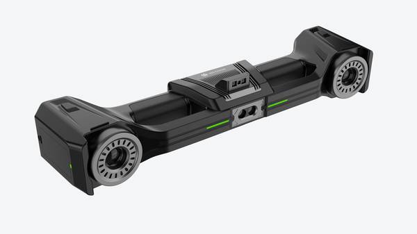
Large-volume tracking systems address wind turbine structure validation, ship components, and large weldments. Here the scanner tracks position over several meters, so you can move around a blade root or tower section without stitching drift. The business case is not speed but coverage. You gain a complete surface record on parts that are impossible to fixture.
Accuracy is generally lower than a stationary lab station, but the relevant question is whether you can hold the surface profile tolerance on a 20-meter structure. Often the answer is yes because the tolerance band is wider.
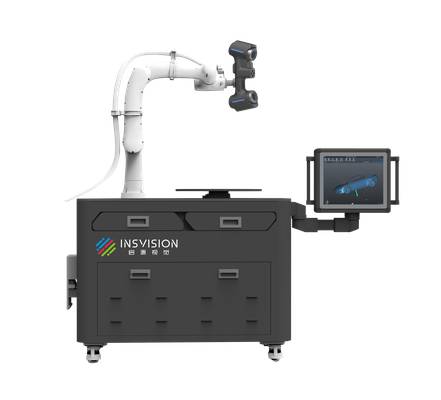
Fixed automated inspection cells are the right choice when batch size and takt time dominate. Automotive component checks, casting lines, and stamped part audits run the same part family repeatedly. A 3D inspection machine mounted in a cell with automated part handling removes operator variation and delivers pass/fail data fast enough for line-side feedback.
The constraint is rigidity: fixtures, part presentation, and environmental stability must be controlled. If your plant already runs SPC on critical dimensions, this configuration plugs into that workflow. INSVISION designs fixed cells around the part profile and the required inspection cycle rather than forcing a standard frame onto the line.
High-precision stationary stations serve medical device tolerance verification, small aerospace components, and first-article inspection where GD&T callouts are tight. The part sits in a temperature-stable area, often on a granite or damped base, and the scanner captures dense point clouds for comparison to CAD.
These stations make sense when you need documented measurement uncertainty, repeatable setups, and data that can support PPAP or ISO/ASME reporting. Throughput is lower, but the deliverable is confidence in the numbers, not parts per hour.
INSVISION engineering teams align each 3D inspection machine configuration to the facility’s workflow, part profiles, and quality standards. The selection process starts with the scan object and the inspection task, then moves to site constraints and required data output. That order prevents the common mistake of buying capability you cannot use or accuracy you cannot verify.
For Western industrial buyers, the practical step is to define the constraint set first: part size, movement, surface condition, cycle time, and reporting requirement. The configuration follows from there.
Structured Validation Steps to Confirm 3D Inspection Machine Performance
Most teams assume a 3D inspection machine is ready for production once the vendor demo looks clean. That assumption causes expensive downstream failures. A structured validation process matters more than the scanner’s published spec sheet.
Start by defining critical part features and tolerance thresholds before any equipment arrives. If you cannot name the GD&T callouts, surface profile limits, and first-article requirements, you are not ready to test anything. Then submit representative sample parts — ideally the same geometry, material, and finish as production — for on-site or lab evaluation under your own acceptance criteria.
Next, verify data output compatibility. Aerospace and automotive teams routinely work in CATIA or SolidWorks; medical device groups often need STEP or IGES exports that survive a PLM handoff. A 3D inspection machine that produces orphan file formats creates rework, not insight.
INSVISION solution teams provide full compatibility details during this phase, so procurement should request a documented data-flow test rather than a verbal assurance.
Finally, cross-check measurement consistency across multiple operators and shifts. Run the same part three times, on two shifts, with different technicians. If repeatability drifts outside your tolerance band, the system will fail in production regardless of lab performance. Formal validation reduces investment risk and confirms the machine integrates with existing quality workflows — not just the metrology lab.
Actionable Decision Checklist for 3D Inspection Machine Selection
When a quality engineer walks a new part through first-article inspection, the conversation usually starts with the CAD model and ends with a stack of dimensional reports. Somewhere in between, the team realizes the current measurement setup cannot hold the tolerance, the part is too large for the granite table, or the takt time does not survive contact with production volume.
A 3D inspection machine purchase should not start with a vendor demo. It should start with five questions answered in writing.
First, define part size range and minimum tolerance thresholds. If the largest casting exceeds the working volume of one scanner position, the system must handle multi-position alignment without accumulating error beyond the tightest GD&T callout. Second, confirm site mobility and installation space. A fixed cell with a 250 kg machine footprint is a different decision than a portable unit moved between workcells.
Third, calculate target inspection takt time and batch volume. A machine that inspects one part in four minutes may be irrelevant if the line releases one part every ninety seconds. Fourth, verify data format compatibility with existing engineering software. IGES, STP, DXF, and DWG support matter when the output feeds FiberSIM or CATIA CPD workflows. Fifth, test scalability for future production line changes.
Adding a new part family should not require a new inspection architecture.
INSVISION solution consulting teams work directly with buyers to walk through this checklist and identify the configuration that aligns with operational priorities. The goal is not to compare spec sheets. The goal is to match the machine to the constraint that actually governs the line.
Hangzhou Insvision Technology Co., Ltd.
Address: Building 1, No. 1399 Liangmu Road, Yuhang District, Hangzhou, Zhejiang 311121, China
Copyright © Hangzhou Insvision Technology Co., Ltd. All rights reserved.
Copyright © Hangzhou Insvision Technology Co., Ltd. All rights reserved.