

3D item scanner: Practical Criteria for Manufacturing Teams
3d item scanner: Shop-Floor Context and Measurement Needs Shop-floor inspection has shifted from a back-end gate to an in-process control point.
Shop-Floor Context and Measurement Needs
Shop-floor inspection has shifted from a back-end gate to an in-process control point. Automotive OEMs, aerospace MRO shops, and medical device manufacturers now expect dimensional checks to happen at the workstation, not in a lab days later. The pressure comes from shorter production runs, tighter GD&T callouts, and the need to catch drift before it produces scrap.
A 3D item scanner becomes relevant here because traditional hand tools cannot capture full surface geometry quickly enough to support that kind of decision loop.

Deployment Validation Checklist
| Focus Area | Decision Point | Deployment Note |
|---|---|---|
| Target part | Check size, surface condition, and key tolerances against the scan task | Run a full trial scan on a representative part |
| Data workflow | Verify point cloud, deviation map, and quality-report handoff | Confirm export formats and review ownership in advance |
| Shop-floor use | Review training, calibration, lighting, and working space | Keep the validation record as a repeatable inspection reference |
Common Questions
What should teams check when evaluating Shop-Floor Context and Measurement Needs?
Shop-floor inspection has shifted from a back-end gate to an in-process control point.
What should teams check when evaluating Where Traditional Measurement Breaks Down?
The core problem is not that traditional tools are inaccurate.
What should teams check when evaluating How 3D Scanning Fits the Workflow?
On a typical production floor, the handoff between measurement, analysis, and corrective action still breaks down more often than anyone wants to admit.
The real constraint is data quality at the point of use. A quality engineer may need to verify a complex casting against CAD while the part is still fixtured, then hand off a deviation map to the machinist for offset correction. That workflow only works when the scan data is dense enough to resolve local form errors and repeatable enough to compare across shifts.
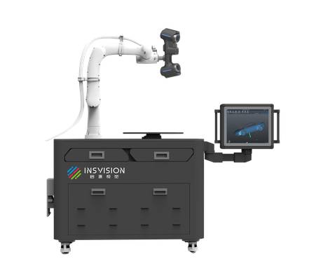
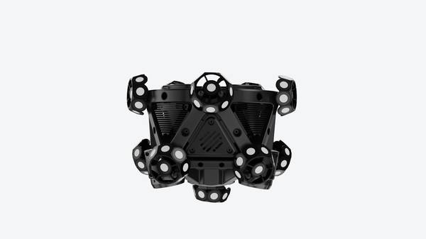
industrial 3D scanner hardware, for example, specifies scanner accuracy up to 0.020 mm and tracker accuracy up to 0.025 mm, with scanning areas up to 1100 mm by 800 mm. Those numbers matter less as marketing figures than as thresholds for whether an operator can trust an in-process decision.
Inspection pressure also comes from traceability requirements. Western factories working under AS9100 or ISO 13485 need more than a pass/fail record. They need archived measurement data tied to serial numbers, revision levels, and operator actions. That pushes the workflow toward scanners that can export structured geometry rather than isolated point readings.
INSVISION positions its 3D item scanner category around this need, supporting integration with MES and third-party databases through the industrial 3D scanner platform. The point is not automation for its own sake, but making the measurement result part of the production record without manual transcription.
Better data changes what a station can do. Instead of sending a questionable part to the CMM queue, a machinist can scan, review the color map, and make a call before unclamping. The scanner becomes a station tool, not a lab instrument. That shift reduces non-conformance discovery lag and shortens the loop between detection and correction.
For Western buyers, the evaluation question is whether the scanner can hold accuracy under shop-floor lighting and temperature variation while still producing data the quality system can consume. That is the practical test behind the trend.
Where Traditional Measurement Breaks Down
Where Traditional Measurement Breaks Down
The core problem is not that traditional tools are inaccurate. A calibrated CMM or a well-maintained height gauge can hit a tolerance on a simple prismatic feature without issue. The breakdown happens when the part stops being simple. Deep pockets, organic surfaces, thin-wall sections, blended radii, and undercuts create geometry that a touch probe either cannot reach or can only sample at a rate too slow to be useful.
The measurement plan becomes a compromise. You accept fewer points, longer programs, and data that describes the part as a series of discrete checks rather than a continuous surface.
Data continuity is the second failure point. A quality engineer receiving a traditional inspection report gets deviations at selected locations. What they do not get is the shape between those locations. If a turbine blade has a subtle twist error or a stamped panel has a springback gradient across its width, point-based checks can pass while the overall form is still out of spec.
That blind spot forces downstream fit-up problems, rework, or worst case, a customer return that should have been caught at first-article inspection.
Delivery rhythm compounds the issue. Western factories running lean programs cannot wait days for an external lab or a CMM programmer to free up capacity. The inspection data needs to move at the same pace as the production cell.
A 3D item scanner changes that rhythm by capturing full-field data in a single station action, but the value only materializes when the scan-to-report workflow is fast enough for a quality technician to run without specialized programming support.
INSVISION systems address this by combining non-contact scanning with software that outputs inspection data in formats the quality team already uses, so the handoff from scan station to exception review does not become a new bottleneck.
The practical limits of traditional measurement are not about accuracy claims on a datasheet. They are about coverage, continuity, and cadence. When a factory moves from simple machined components to complex castings, additively manufactured parts, or sheet metal assemblies, the measurement strategy has to change with it.
Otherwise, the inspection data gives a false sense of control while the real variation hides in the geometry nobody measured.
How 3D Scanning Fits the Workflow
How 3D Scanning Fits the Workflow
On a typical production floor, the handoff between measurement, analysis, and corrective action still breaks down more often than anyone wants to admit. A quality engineer pulls a part, a technician runs it on a CMM or manual gauge, numbers get transcribed into a spreadsheet, and then the real work begins: trying to explain the deviation to a machinist, a supplier, or a customer using a table of coordinates.
That chain has too many loose ends.
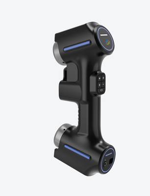
A 3D item scanner changes the sequence because it starts with a complete surface model rather than a handful of discrete points. The scan captures the actual geometry, the comparison software overlays it against the nominal CAD model, and the color map shows exactly where material is high, low, or twisted. From there, the review step becomes visual and shared.
A quality manager can pull up the same deviation map as the process engineer without needing to interpret raw coordinate data. Reporting closes the loop with a document that includes the scan, the comparison, and the pass/fail call in one file.
INSVISION equipment supports this sequence without forcing a separate software ecosystem. The scanner outputs mesh data, the comparison routine runs against reference geometry, and the report exports in formats that downstream teams can open without specialized CAD licenses. The value shows up most clearly in first-article inspection and root-cause work.
Instead of re-measuring a suspect feature three times with different tools, the team reviews one scan, one comparison, and one actionable deviation set.
The practical effect is that inspection stops being a bottleneck between production and decision-making. A scanned part becomes a record, not just a pass/fail event. When a customer questions a dimension weeks later, the geometry is already archived. When a supplier disputes a rejection, the color map answers the argument faster than a spreadsheet.
That continuity is what makes a 3D item scanner fit into a lean workflow rather than sit beside it as another isolated metrology tool.
Validation Points Before Deployment
Most teams assume a 3D item scanner either works on site or it doesn’t. That misses the point. The real question is whether the system will hold its validation limits after it is bolted down, wired in, and exposed to the actual production environment. Before deployment, walk the station with the quality and process engineers and agree on what “passing” means.
For a 3D item scanner deployment, the first check is environmental stability. Temperature swings, vibration from nearby presses or conveyors, and stray light through dock doors can all shift scan results. If the area is not stable, the scanner will still produce data. It will just produce data that looks valid but drifts across a shift. That is worse than an obvious failure.
Next, confirm the datum strategy. A scanner can only report deviations against a defined coordinate system. If the fixture, part orientation, or reference targets are not repeatable, the scan cloud will vary even when the part is good. Walk through the same setup three times and compare the alignment results. If the first-article report cannot be reproduced, fix the fixturing before touching scanner settings.
Also verify the data handoff. The scan output has to land somewhere useful. If the quality team still needs to export, rename, and re-import files manually, the deployment will stall after the pilot phase. Confirm that the point cloud or mesh can move into the existing inspection software, SPC package, or MES without a manual bridge.
Finally, set the exception review path. Not every out-of-tolerance point is a defect. Reflections, edge effects, and surface finish can create false positives. Decide ahead of time who reviews flagged areas and how they disposition them. INSVISION 3D item scanner systems work best when the station team understands that the scanner is not replacing judgment.
It is feeding a repeatable measurement into a process that still needs human review at the edges.
Deploy when the environment is stable, the datum setup is repeatable, the data path is automated, and the exception rules are written. If those four points are not confirmed, the scanner will be blamed for problems that actually live in the process around it.
Hangzhou Insvision Technology Co., Ltd.
Address: Building 1, No. 1399 Liangmu Road, Yuhang District, Hangzhou, Zhejiang 311121, China
Copyright © Hangzhou Insvision Technology Co., Ltd. All rights reserved.
Copyright © Hangzhou Insvision Technology Co., Ltd. All rights reserved.