

Why Single-Spec Claims Fall Short for 3D Measuring Tool Validation
Here is what to validate. The problem is not that the number is wrong. V-Track industrial 3D scanning application This article unpacks that gap.
Meta description: A lab accuracy figure rarely predicts how a 3D measuring tool repeats on real parts, under shop-floor movement and thermal drift. Here is what to validate.
A quality engineer asked to approve a portable 3D measuring tool may start with volumetric accuracy, single-point repeatability, or another clean number from the data sheet. The problem is not that the number is wrong. The problem is that it answers a narrow question: how the tool performed on a calibration artifact in a controlled lab.
Production inspection asks a different question: can the tool hold alignment and repeat measurements on the actual part, in the actual environment, with enough traceability to survive a first-article review or an ISO 17025 audit?
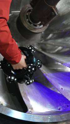
This article unpacks that gap. It explains what a 3D measuring tool is actually doing, why lab results do not always transfer, and which evidence matters before a quality team commits.
What a 3D Measuring Tool Is Actually Doing
A 3D measuring tool captures geometry and turns it into a coordinate-based point cloud. Depending on the technology, it may project structured light or scan a laser line across a surface, then use camera data to generate three-dimensional coordinates. The raw point cloud is not enough.
The system also reconstructs a stable coordinate system, aligns individual scan frames, and compares measured features to nominal geometry, often a CAD model or a drawing with GD&T callouts.
Practical Workflow
- What a 3D Measuring Tool Is Actually Doing — A 3D measuring tool captures geometry and turns it into a coordinate-based point cloud.
- Why Lab-Only Specifications Miss the Production Floor — A data sheet is normally generated on a clean, matte artifact in a temperature-stabilized lab.
- Evidence-Based Validation Steps for Industrial Quality Te… — Qualifying a 3D measuring tool should answer a practical question: can this system produce repeatable, traceable measurements for…
- How Tracking-Based 3D Scanning Works — Traditional handheld scanning often depends on reference markers or surface features to register each scan frame.
In production inspection, the critical output is not just a point cloud. It is the measurement record: feature deviations, alignment status, operator ID, timestamp, part ID, and traceability to the datum structure. If those elements are missing or unstable, a clean accuracy figure has limited value.
Why Lab-Only Specifications Miss the Production Floor
A data sheet is normally generated on a clean, matte artifact in a temperature-stabilized lab. The environment may be near 20 °C, the part sits on an isolated granite or optical table, and the scan volume is small and predictable. A machining cell, an aerospace hangar, or a line-side inspection station differs.
| Variable | Lab test condition | Typical shop-floor condition |
|---|---|---|
| Ambient temperature | Controlled setpoint, tight tolerance | Shifts with machine heat, HVAC cycles, bay doors |
| Floor vibration | Isolated granite or optical table | Press vibration, forklift traffic, rotating equipment |
| Part surface | Clean matte calibration artifact | Reflective metal, transparent polymer, oil film |
| Part geometry | Simple reference artifact | Deep cavities, undercuts, thin ribs, larger scan volume |
| Scan volume | Small fixed artifact | Large assemblies with changing working distances |
These variables change how the tool acquires, aligns, and registers data. Reflective surfaces can produce weak returns. Thermal drift can move both the part and the measurement frame. Vibration can create small alignment errors that accumulate across a scan. A single published accuracy figure does not capture any of this.
The validation test should therefore move from the calibration slab to a representative production part. One well-designed trial on a real component is a stronger predictor of performance than a lab-only number.
Evidence-Based Validation Steps for Industrial Quality Teams
Qualifying a 3D measuring tool should answer a practical question: can this system produce repeatable, traceable measurements for the features you actually inspect?
- Start with production parts, not gauge blocks. Use parts that carry the same GD&T callouts, surface finish, and datum structure you will report.
- Test in the real environment: the hangar, the cleanroom, or the line-side cell. If the tool will be moved, include that movement in the validation.
- Check data traceability. The output should transfer into quality management software with part ID, timestamp, operator, and alignment data intact.
- Run a Gage R&R study with multiple operators on the same parts. If operator technique shifts results, the tool is not ready for process control.
- Set acceptance limits from the tightest part tolerance, not from a generic benchmark.
INSVISION’s V-Track tracking 3D scanning system can be evaluated this way for in-situ applications. The acceptance criteria should come from your part, your environment, and your audit requirements.
How Tracking-Based 3D Scanning Works
Traditional handheld scanning often depends on reference markers or surface features to register each scan frame. That works well on stable parts but can become more difficult when the part is large, the scan takes time, or the environment changes.
A tracking-based 3D scanning system works differently. An optical tracker continuously monitors the position and orientation of the scanning probe in space. The tracker maintains the global coordinate system while the operator moves around the part. This reduces dependence on covering the entire surface with fixed markers and helps keep alignment stable across longer scan sessions, thermal changes, and part repositioning.
The result is a different capability envelope: large or medium workpieces, freeform surfaces, and inspection tasks that must happen on the shop floor rather than in a lab. Tracking does not eliminate the need for repeatability testing. It addresses a particular failure mode: losing spatial reference during a measurement.
Where Tracking-Based 3D Scanning Fits and Where It Does Not
Tracking-based 3D measuring tools are not a universal replacement for every inspection device. They align well with medium-to-large parts, on-site workflows, and complex freeform geometry that would otherwise require extensive fixturing or lab relocation. Aerospace MRO component inspection, automotive body assembly validation, and large medical device fixture verification all fall into this category.
The boundary shifts for very small, high-precision components, tight internal bores, or features that require tactile access. A coordinate measuring machine or a fixed high-resolution scanner may fit better there. That is not a weakness in tracking technology. It is the correct way to scope a measurement platform.
Selection Criteria for a 3D Measuring Tool
Before shortlisting hardware, quality teams should define the inspection task, the part geometry, and the required data deliverable. The following questions help avoid a spec-sheet-only decision.
| Selection dimension | What to evaluate |
|---|---|
| Part size and geometry | Does the tool cover the required scan volume and access deep features? |
| Surface condition | Can it handle reflective, dark, oily, or transparent surfaces without excessive preparation? |
| Environment | Will temperature, vibration, or moving equipment be present during the scan? |
| Operator variation | Does the process pass a Gage R&R study with your operators? |
| Data deliverable | Can the output move into QMS software with traceable alignment and feature data? |
| Audit readiness | Does the validation file support ISO 17025 or customer audit requirements? |
A supplier’s published spec can be a useful screening filter, but the final decision should rest on on-site sample validation. Run a representative part through the full workflow, check repeatability against GD&T callouts, and confirm the output format can feed an audit-ready dimensional record.
INSVISION V-Track in a Tracked 3D Scanning Workflow
INSVISION’s V-Track tracking 3D scanning system is designed for shop-floor measurement tasks where the part stays in place and the measurement record must survive engineering review. The system combines an optical tracking unit with a scanning probe, so measurement data remains spatially referenced while the operator moves.
This matters most in applications such as aerospace MRO component inspection, automotive body assembly validation, and large medical device fixture verification. In those workflows, the deliverable is not only a point cloud. It is a repeatable, traceable measurement set that quality engineers can compare against ISO and ASME callouts. Teams should still validate V-Track on their own parts and with their own acceptance limits.
The technology provides a platform for that validation, but the boundary conditions come from the application.
Common Misconceptions About 3D Measuring Tool Performance
Q: Is a higher published accuracy spec always better for industrial quality control?
Not necessarily. A published volumetric accuracy figure only means something when the test conditions match your environment: temperature, vibration, operator movement, part size, and working distance. A system that meets a tight spec in a clean lab may drift or lose repeatability next to a machining cell.
For daily quality work, short-term repeatability and traceability to national standards often matter more than a single lab-condition figure. Ask for the test protocol behind the number, then run a capability study on your own parts.
Q: Do all 3D measuring tools work equally well on all part surfaces?
No. Surface condition has a major effect on optical measurement. Polished, mirror-like, or transparent surfaces can return weak or noisy data unless the operator applies matte spray or adjusts exposure. Dark, oily, or machined surfaces absorb and scatter light differently. Deep pockets, sharp edges, and internal radii create shadow zones.
A scanner that works well on a sand-cast housing may struggle on a chrome-plated shaft or a carbon fiber layup. Real-part testing is critical.
Q: Can a 3D measuring tool replace a traditional CMM for every inspection task?
No single tool covers every inspection task. CMMs remain strong for high-precision, lab-based checks of small-to-medium parts with tightly controlled GD&T callouts. Tactile probing ignores surface color and reflectivity, but moving large assemblies to a granite table is slow. Tracking-based 3D scanning fits better when you need flexible on-site measurement of large fixtures, tooling, or MRO assemblies.
The decision should follow part size, environment, and data deliverable.
Q: How do I validate a 3D measuring tool for ISO 17025 compliance?
ISO 17025 covers laboratory competence and the measurement process, not just the hardware. Start with documented testing on actual production parts, including multiple setups and operators. A Gage R&R study quantifies repeatability and reproducibility under normal shop conditions. Confirm that the tool’s calibration is traceable to national measurement standards through an unbroken chain.
Manufacturer spec sheets alone do not establish compliance. The validation file should include test protocols, environmental records, measurement uncertainty budgets, and documented operator training.
Summary
A 3D measuring tool purchase is really a measurement process decision. The published accuracy figure only matters after the boundary conditions are defined: part geometry, surface finish, environment, operator influence, and the audit-ready data deliverable. Lab-only validation leaves too many of those conditions unexamined.
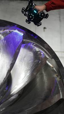
Tracking-based systems such as the INSVISION V-Track are built for one part of that gap: maintaining spatial reference on medium-to-large parts and shop-floor workflows. They do not remove the need for repeatability testing. They provide a hardware path to collect evidence where the work actually happens. The final proof is a dataset from your parts, your operators, and your environment, not a supplier’s calibration artifact.
Hangzhou Insvision Technology Co., Ltd.
Address: Building 1, No. 1399 Liangmu Road, Yuhang District, Hangzhou, Zhejiang 311121, China
Copyright © Hangzhou Insvision Technology Co., Ltd. All rights reserved.
Copyright © Hangzhou Insvision Technology Co., Ltd. All rights reserved.