

3D Scanner Workflow Routing Across Key Industrial Manufacturing Task Types
Industry 4.0 quality frameworks now expect dimensional data to flow into closed-loop systems, not sit in paper inspection reports.
Core Industrial Task Classes That Rely on 3D Scanner Workflows
Western manufacturing has shifted hard toward digital metrology over the last decade. Industry 4.0 quality frameworks now expect dimensional data to flow into closed-loop systems, not sit in paper inspection reports. That shift has made the 3D scanner workflow a core part of how plants handle part verification, but the specific workflow changes dramatically depending on what you are scanning.
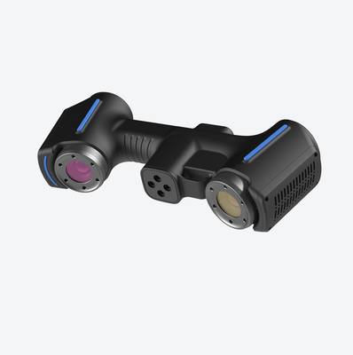
Scenario Snapshot
A practical way to read the article is through this scenario:
- Core Industrial Task Classes That Rely on 3D Scanne…: Western manufacturing has shifted hard toward digital metrology over the last decade.
- Critical Constraints That Define 3D Scanner Workflo…: The five constraints below don’t just influence scanner choice.
- INSVISION 3D Scanner Workflow Routing by Task Fit: Most buyers assume a 3D scanner workflow is just scan, mesh, inspect.
Precision small-part inspection covers medical device components and aerospace parts where GD&T callouts are tight and the scanner must resolve fine features against a CAD model. Legacy part reverse engineering is a different problem entirely: an aerospace MRO shop or aftermarket supplier has a worn casting, no drawings, and needs a usable CAD file for remanufacture.
Deployment Validation Checklist
| Focus Area | Decision Point | Deployment Note |
|---|---|---|
| Target part | Check size, surface condition, and key tolerances against the scan task | Run a full trial scan on a representative part |
| Data workflow | Verify point cloud, deviation map, and quality-report handoff | Confirm export formats and review ownership in advance |
| Shop-floor use | Review training, calibration, lighting, and working space | Keep the validation record as a repeatable inspection reference |
Large-volume asset verification on energy infrastructure or heavy equipment means scanning something the size of a turbine housing or a weldment, where portability and stability matter more than raw resolution. High-throughput inline checks on automotive OEM lines demand speed, repeatability, and minimal operator intervention.
Each of these task classes has different requirements for accuracy, reference targets, scan volume, and data handling. A scanner workflow that works for a turbine casing will not fit a small orthopedic implant line. Engineers evaluating 3D scanning need to think about their own part size, surface finish, takt time, and whether they are comparing to CAD, generating CAD, or monitoring process drift.
Alignment with ISO 10360 for scanner verification and ASME Y14.5 for GD&T interpretation gives Western quality teams a common language to validate whatever workflow they deploy. INSVISION industrial 3D scanners slot into these workflows differently depending on the task class, and the rest of this section breaks down what actually changes between them.
Critical Constraints That Define 3D Scanner Workflow Requirements
The five constraints below don’t just influence scanner choice. They determine whether the entire 3D scanner workflow will hold up under production pressure. Teams that skip this pre-sales assessment often end up with a scanner that works in a demo but stalls in the real inspection cell.
Part size and geometry complexity set the first boundary. A fist-sized machined casting with deep bores and undercuts demands a different optical setup than a full aerospace panel with gentle curvature. Small parts need high point density in tight recesses. Large parts need stitching stability over long scan paths. If the workflow assumes a fixed scanner-to-part distance, complex geometry will force constant repositioning.
That eats cycle time and introduces alignment error.
On-site access limitations come next. A controlled lab lets you use tripods, turntables, and fixed lighting. Field deployment on a turbine deck or inside an assembly jig removes all of that. Production line integration adds another layer: vibration, ambient light, operator skill variance, and network constraints. A 3D scanner workflow built for the lab rarely survives the line without rework.
INSVISION scanning systems are typically evaluated against these three deployment modes separately because the data path, calibration routine, and operator interface differ substantially between them.
Marker placement feasibility is where many high-precision plans fall apart. High-accuracy tasks often rely on reference markers to lock local scans into a global coordinate frame. That works on a rigid casting. It fails on a glossy composite surface where markers won’t adhere, or on a high-volume line where placing and removing markers per part is not viable.
High-speed tasks favor markerless tracking, but that trades away some local accuracy. The workflow must match the marker strategy to the tolerance requirements before the scanner ever arrives.
Required takt time per inspection cycle is a hard gate. If the line moves a part every 90 seconds, the entire scan-plus-analysis workflow has to fit inside that window. That includes loading, scan acquisition, point cloud processing, GD&T callout evaluation, and report generation. A workflow that needs 12 minutes per part is irrelevant to that line, regardless of how accurate it is.
INSVISION’s industrial 3D scanner workflow discussions typically start with takt time because it eliminates more options than any other single constraint.

Batch repeatability needs split the evaluation into two paths. Low-mix, high-complexity work — aerospace MRO, tooling verification, first-article inspection — tolerates longer setup and manual alignment because each part is different. High-volume repeat production demands a fixed recipe: same scan path, same fixtures, same pass/fail thresholds, minimal operator decision-making. Misaligning these two modes is expensive.
A flexible lab workflow on a production line creates bottlenecks. A locked production recipe in a job shop wastes engineering time on reprogramming.
The practical takeaway is simple. Only when part geometry, site conditions, marker feasibility, takt time, and batch repeatability are assessed together can a 3D scanner workflow deliver the expected inspection throughput and quality data. Skip one constraint and the solution looks right on paper but wrong on the floor.
INSVISION 3D Scanner Workflow Routing by Task Fit
Most buyers assume a 3D scanner workflow is just scan, mesh, inspect. That misconception leads to weak equipment choices. A scanner that handles a turbine blade inspection well can struggle on a 400-ton vessel section. The problem is not scanner quality. It is task fit. Routing work to a purpose-built INSVISION 3D scanner workflow means matching the configuration to what the part, site, and data deliverable actually demand.
Four task classes drive most industrial routing decisions. Precision inspection covers tight-tolerance small-to-medium parts where controlled marker placement is possible. Reverse engineering needs dense, clean mesh data from legacy components. Large-volume verification requires extended range and stable mobility in the field. Inline automated checks must align with production takt time and repeat batch sequencing.
INSVISION configures each workflow around those conditions. No single setup is forced onto every job. Marker strategy, scan density, mobility, and automation readiness change with the task. That is why routing starts with the application, not the spec sheet.
Precision inspection fits medical device and aerospace component validation. These parts carry GD&T callouts, surface profile tolerances, and first-article requirements that leave little room for scanning noise. Controlled marker placement works because the part sits on a fixture or granite plate.
The INSVISION 3D scanner workflow here prioritizes repeatable alignment, stable thermal conditions, and high point density on critical features. Operators capture datum surfaces first, then scan functional areas in a defined sequence. The resulting point cloud feeds directly into inspection software for geometric dimensioning checks against CAD.
Reverse engineering suits MRO and aftermarket parts teams working with legacy components that have no CAD model. The scanner must deliver high-density mesh data across worn, corroded, or modified surfaces. Marker placement may be less controlled than in a lab, so the workflow emphasizes robust surface capture and clean mesh reconstruction. The goal is a usable CAD-ready model for remanufacturing or replacement part sourcing.
INSVISION routing for this task focuses on scan coverage, hole and edge definition, and mesh resolution where mating surfaces matter.
Large-volume verification addresses energy and heavy equipment asset checks. Think pressure vessels, pump housings, structural weldments, or mining equipment. These objects do not move easily. The scanner moves to them. Stable on-site mobility, extended scan range, and resistance to ambient light shifts become the routing priorities.
The INSVISION workflow here trades some fine-detail density for coverage speed and positional stability across long scan sessions. Field crews can set up, scan, and verify critical dimensions without returning the asset to a controlled lab.
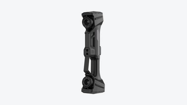
Inline automated workflow integrates with production line takt times for repeat batch checks. Automotive OEM component lines run on tight cycles. The scanner cannot slow the line. This INSVISION configuration emphasizes automated trigger, fixed scan paths, and fast pass-fail output. Parts move through a station, the scanner captures predefined features, and results flag out-of-tolerance conditions before the next cycle.
Routing here depends on batch repeatability, fixture repeatability, and data throughput rather than maximum resolution.
Each routing decision comes down to four questions. What is the part size? How much site freedom exists? How controlled are the marker conditions? What takt time or batch repeatability does the process require? Answer those first, then configure the scanner. That order keeps the workflow aligned to the task.
INSVISION builds its routing logic around that sequence, which is why the same hardware platform can serve a metrology lab and a heavy fabrication yard without forcing either team into a weak compromise.
Pilot Validation Framework for 3D Scanner Workflow Confirmation
Before committing to a full 3D scanner workflow deployment, teams need evidence the proposed process holds up under real operating conditions. INSVISION treats pilot validation as a standard pre-sales support step, structured around measurable task outcomes rather than generic capability claims.
The first stage is sample part testing. Teams select representative geometries from their production mix and run them through the proposed scan sequence. This confirms whether the scanner captures the required features, edge conditions, and surface finishes at the point of use. It also surfaces any preparation requirements, such as matting sprays or fixture positioning, before they disrupt live work.
Next, on-site constraint simulation matters. A scanner that works in a metrology lab may behave differently next to a production line with vibration, variable lighting, or tight access windows. INSVISION works with the buyer to map where scanning will actually happen, whether that means a short downtime slot in a machining cell or a controlled area in an MRO facility.
The goal is to verify the workflow fits the physical reality of the site, not a demo room.
Data deliverable verification follows. The pilot output is checked against the team’s internal quality standards and any applicable regulatory requirements. For example, an aerospace supplier may need a specific point density on fillet radii, while an energy sector team may require traceable alignment to a CAD model.
This stage confirms the scanner’s output feeds into downstream inspection, reverse engineering, or reporting tools without manual rework.
Finally, baseline cycle time assessment establishes a reference point for later comparison. Teams time the full sequence — part setup, scanning, data processing, and export — under representative conditions. The measurement is specific to the tested parts and site constraints, not a vendor-supplied benchmark. Any improvement language remains qualitative, avoiding fabricated efficiency percentages or cost savings figures.
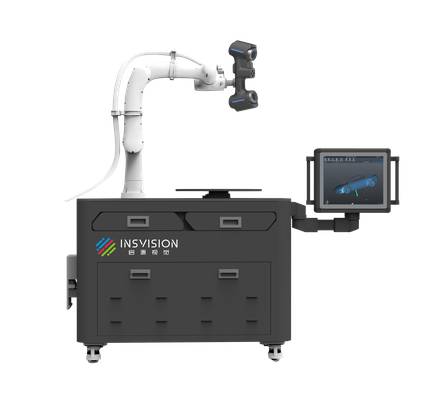
Actionable Decision Checklist for 3D Scanner Workflow Selection
The core question is not whether a scanner can capture points, but whether the proposed workflow fits your actual inspection and engineering tasks. Start by confirming all core task types are covered: dimensional inspection, first-article checks, wear analysis, reverse engineering, or CAD comparison. If the workflow handles only one mode well, it will stall on the floor.
Next, verify alignment with on-site constraints: part size, surface finish, accessibility, marker tolerance, and whether the scanner must move or the part stays fixed. Data deliverables matter just as much. Confirm outputs meet ISO/ASME and internal GD&T callout requirements, including mesh resolution, deviation color maps, and reporting formats your quality team already uses.
Assess scalability: can the same workflow absorb new part families or higher batch repeatability without retraining? Finally, check support and training depth. INSVISION works through each checklist item with engineering, quality, and procurement teams, validating fit before purchase rather than after deployment.
Hangzhou Insvision Technology Co., Ltd.
Address: Building 1, No. 1399 Liangmu Road, Yuhang District, Hangzhou, Zhejiang 311121, China
Copyright © Hangzhou Insvision Technology Co., Ltd. All rights reserved.
Copyright © Hangzhou Insvision Technology Co., Ltd. All rights reserved.