

Why Pre-Deployment Validation Separates Reliable 3D Scanning for Vehicle Frames from Guesswork
3D scanning for vehicle frames: For frame engineering and quality teams, the difference between a useful scan and an impressive-looking point cloud often.
Where Vehicle Frame Scanning Creates Engineering Value
3D scanning for vehicle frames is not a single application. Dimensional inspection against ISO 10360 and ASME Y14.5 GD&T callouts requires scan data aligned to CAD datums and reported through traceable feature control frames. A dense point cloud alone is not enough. Deformation and assembly gap analysis on welded frames also matters: heat input, clamping sequence, and springback create small deviations that affect function.
Mapping those conditions across the full assembly helps engineering teams decide where correction is required.
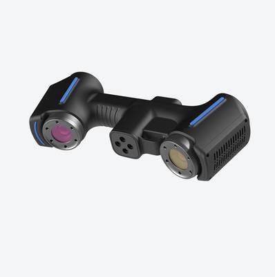
Scenario Snapshot
A practical way to read the article is through this scenario:
- Where Vehicle Frame Scanning Creates Engineering Va…: 3D scanning for vehicle frames is not a single application.
- Why the Production Floor Changes Scan Behavior: A scanning system that works in a controlled lab can struggle next to a fixtured frame on a production line.
- Capture Risks That Turn a Point Cloud into a Visual…: Alignment drift is often the first risk engineers notice in 3D scanning for vehicle frames.
Reverse engineering of legacy or modified frames is a third workflow. When drawings are missing or a frame has been altered in service, scan-to-CAD outputs give a usable reference for new brackets, reinforcements, or replacement parts. Some plants also use scanning as part of tool and fixture validation before committing to a broader quality program.
In each case, surface finish, access, scan distance, and deliverable format determine fit as much as accuracy on a calibration artifact.
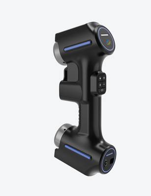
Why the Production Floor Changes Scan Behavior
A scanning system that works in a controlled lab can struggle next to a fixtured frame on a production line. The object itself is not a single clean surface. Bare steel, aluminum castings, machined cast iron, and painted or e-coated finishes respond differently to structured light. Weld seams, undercarriage mounting points, and threaded holes create occlusions that force multiple scan positions and careful alignment.
On the floor, conditions add another layer. Vibration from nearby operations can disturb long captures. Ambient light can shift between shifts and change exposure behavior. Access around a fixtured frame is typically limited, and any measurement step must avoid disrupting line takt. Data also needs to flow into existing CAD and QMS systems.
These constraints are why validation should happen in the actual production environment, not on a bench in an applications lab.
Capture Risks That Turn a Point Cloud into a Visual Model
Alignment drift is often the first risk engineers notice in 3D scanning for vehicle frames. Long rails and broad crossmembers offer limited stable geometry for alignment. Small angular errors accumulate over distance, and by the far end of a frame, GD&T position or profile results may fall outside usable tolerance. The point cloud can look complete while the measurement is not reliable.
Missed fine features are a common failure. Weld toes, small holes, and bracket edges can disappear in noisy or under-resolved passes. The dataset may appear dense, but the inspection report remains incomplete. Occluded zones around crossmembers and suspension mounts can force repeated repositioning of the frame. More lifting means more labor and higher safety exposure.
Extended preparation and patch scanning also create a conflict with production throughput targets.
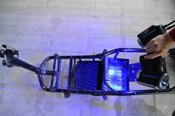
These risks are manageable when validation defines datum alignment, capture sequence, and rescan triggers before production scanning begins. Without that discipline, the output is a visual model rather than dimensional data.
Where AlphaScan Fits the Frame Inspection Workflow
For many frame inspection tasks, a handheld scanner such as INSVISION AlphaScan changes the access equation. A fixtured vehicle frame is awkward to reposition, and flipping it to reach an undercarriage weld seam can introduce datum shift and safety risk. AlphaScan moves around the part instead of requiring the part to move around the scanner.
That handheld form factor helps engineers reach occluded undercarriage zones and weld root areas without breaking the existing fixture alignment. Portability also supports scanning on the production floor, in a quality lab, or at a durability test area. Large frames do not need to be transported to a dedicated inspection station.
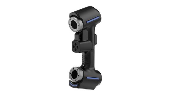
Final selection still depends on sample validation against part-specific tolerances and deliverable requirements. INSVISION AlphaScan is not a blanket guarantee for every frame program, but its design matches many of the access and handling constraints engineers encounter on the shop floor.
Pre-Deployment Validation in Five Stages
A practical validation plan for 3D scanning for vehicle frames should cover five stages. The goal is to confirm that data remains reliable from the first scan to the final report under production conditions.
| Stage | What to Verify | Acceptance Focus |
|---|---|---|
| 1. Define control points | Map GD&T callouts, weld seam profiles, and assembly gap locations on a representative frame | Are critical features identified before scanning? |
| 2. Scan in the real environment | Run test captures in the same lighting, vibration, and access conditions as production | Does the scanner hold up outside a controlled lab? |
| 3. Check alignment accuracy | Use reference markers across the full frame length, including distant control points | Does registration drift stay within tolerance? |
| 4. Test data interoperability | Import scan data into existing CAD and QMS platforms | Can engineers use the output without manual rework? |
| 5. Assess workflow efficiency | Cover preparation, scanning, processing, and reporting against internal throughput needs | Can the process fit the production schedule? |
This type of sample validation aligns with ISO dimensional inspection expectations and gives engineering teams a defensible basis for adopting a scanning workflow.
Practical Boundaries for Handheld Frame Scanning
Handheld 3D scanning for vehicle frames with INSVISION AlphaScan fits targeted dimensional work most naturally. On assembled frames, that includes on-demand spot inspection on the shop floor: checking critical GD&T callouts, hole positions, or fixture alignment after a setup change. It also supports deformation analysis after crash or durability testing, where the priority is localized buckling, twist, or mount point shift.
Comparing the scan against pre-test CAD gives engineers a clear view of how the structure changed.
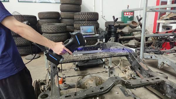
Reverse engineering of legacy or custom frame designs is another practical use case, especially when original drawings are unavailable. For plants building their first scanning workflow, AlphaScan can support pre-purchase tool evaluation. Quality and engineering teams can test scan-to-CAD alignment, repeatability, and export practice before committing to wider rollout.
Teams with unusual frame geometry or narrow tolerance requirements should work with INSVISION application engineers to tailor a validation plan around specific datums, reference features, and acceptance criteria. That keeps the system aligned with internal quality and productivity goals.
Final Takeaway for Frame Engineering Teams
Dimensional inspection on vehicle frames is rarely solved by a specification sheet. Mixed materials, long geometry, weld-affected surfaces, and production floor conditions all influence whether a scan produces trustworthy measurement data. Pre-deployment validation is the control point: it defines what will be scanned, how alignment will be checked, and what constitutes an acceptable result.
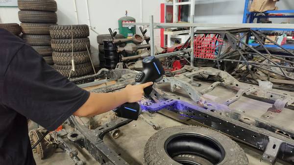
For teams evaluating 3D scanning for vehicle frames, the most defensible approach is to start with a representative frame, run the scan in the actual production environment, and verify the output against existing CAD and QMS workflows. INSVISION AlphaScan addresses many of the access and handling constraints that derail frame measurement, but it should still earn its place through a structured, part-specific validation.
That is the difference between collecting point clouds and producing dimensional data that engineers can act on.
Hangzhou Insvision Technology Co., Ltd.
Address: Building 1, No. 1399 Liangmu Road, Yuhang District, Hangzhou, Zhejiang 311121, China
Copyright © Hangzhou Insvision Technology Co., Ltd. All rights reserved.
Copyright © Hangzhou Insvision Technology Co., Ltd. All rights reserved.