

Reducing Rework and Inspection Bottlenecks with 3D Scanning Pipe Welds
Reducing Rework and Inspection Bottlenecks with 3D Scanning Pipe Welds. Most plants that adopt 3D scanning for pipe weld inspection do so expecting faster cycle times.
Hidden Delivery Risks in Pipe Weld 3D Scanning Workflow Integrations
The real cost overruns hide in the gaps between the scanner and the existing quality ecosystem. Take ASME B31.3 or ISO 5817 compliance. A scanner can capture every ripple and toe angle on a pipe weld, but if the software cannot map those measurements to the correct acceptance criteria automatically, an inspector still has to manually cross-reference code tables.
That single step erases a significant chunk of the time savings the hardware was supposed to deliver. The same pattern appears with on-site access constraints. A scanner spec sheet might claim a 500 mm standoff distance, but that number means nothing when a pipe rack leaves 300 mm of clearance on one side and the scanner needs line-of-sight from two angles.
The investment sits idle while inspectors fall back to calipers and pit gauges — an invisible cost that never appears on the purchase order.
Deployment Validation Checklist
| Focus Area | Decision Point | Deployment Note |
|---|---|---|
| Target part | Check size, surface condition, and key tolerances against the scan task | Run a full trial scan on a representative part |
| Data workflow | Verify point cloud, deviation map, and quality-report handoff | Confirm export formats and review ownership in advance |
| Shop-floor use | Review training, calibration, lighting, and working space | Keep the validation record as a repeatable inspection reference |
Practical Workflow
- Hidden Delivery Risks in Pipe Weld 3D Scanning Workflow I… — The real cost overruns hide in the gaps between the scanner and the existing quality ecosystem.
- On-Site Sample Validation: Aligning Scan Performance to W… — Structured on-site sample validation is the first critical check to prevent implementation gaps when rolling out 3D scanning pipe…
- Workflow Integration: Connecting 3D Scan Data to Existing… — Integrating 3D scanning into pipe weld quality workflows does not require tearing up your current system.
Then there is the data handoff problem — the one nobody budgets for during procurement. Most scanning systems export point clouds or mesh files. A quality management system expecting pass/fail reports with lot traceability, heat numbers, and inspector sign-offs in a specific ERP format cannot ingest raw scan data. Someone has to sit between the scanner and the QMS, manually reformatting outputs.
That role becomes a permanent headcount, quietly eating the labor savings the project was supposed to generate.
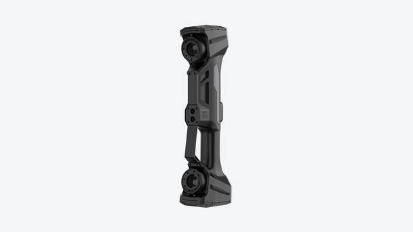
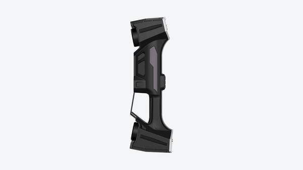
INSVISION confronts this directly by engineering the AlphaVista large-format handheld scanner around the full inspection workflow rather than treating scan acquisition as the endpoint. The system aligns scan data to ASME B31.3 and ISO 5817 acceptance criteria automatically, removing the manual cross-referencing step.
Its handheld design eliminates fixed station setup, so a technician can navigate confined pipe racks and capture usable data even when clearance is tight. The output is not a raw point cloud; it is a structured inspection record that plugs into the quality management tools already running on the shop floor.
On-Site Sample Validation: Aligning Scan Performance to Weld Quality Requirements
Structured on-site sample validation is the first critical check to prevent implementation gaps when rolling out 3D scanning pipe welds. Select representative test samples spanning your full operational range: small-bore process piping to large-diameter transmission mains, butt, fillet, and socket weld joints, and samples with documented defects (porosity, misalignment, undercut) aligned to ISO or ASME quality standards.
Validate against three core criteria: capture reliability in real site conditions (confined pipe racks, reflective steel, fluctuating plant lighting), alignment of scan data with calibrated baseline tools, and capture speed relative to production takt time. The INSVISION AlphaVista handheld scanner fits this use case well;
its design supports flexible scanning of small and large pipe welds across industrial environments without repositioning a fixed station. Note that complex deep-undercut joints may need extra passes for full data continuity, so build small buffers into validation delivery rhythms for high-complexity batches.
Catching these limitations during validation prevents the much larger cost of missed defects found later in hydrotest or field service.
Workflow Integration: Connecting 3D Scan Data to Existing Quality and Compliance Systems
Integrating 3D scanning into pipe weld quality workflows does not require tearing up your current system. The data outputs from INSVISION’s scanning tools are built to feed directly into the CAD and QMS platforms already running on Western manufacturing floors.
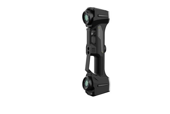
Scans produce standard mesh files that align with common inspection software, making it straightforward to overlay as-built geometry against nominal CAD models and flag deviations against GD&T callouts. Automated inspection reports generate color maps and pass/fail tables structured to match ISO 5817 or ASME B31.3 acceptance criteria.
Hangzhou Insvision Technology Co., Ltd.
Address: Building 1, No. 1399 Liangmu Road, Yuhang District, Hangzhou, Zhejiang 311121, China
Copyright © Hangzhou Insvision Technology Co., Ltd. All rights reserved.
Copyright © Hangzhou Insvision Technology Co., Ltd. All rights reserved.