

The Hidden Cost of a Single-Spec Rating in 3D Scanning Large Welded Structures
Why a Static Accuracy Spec Fails on the Shop Floor Large welded structures introduce variables that a lab-tested accuracy rating cannot replicate.
That number, typically measured in a temperature-controlled lab on a granite surface plate, says almost nothing about how the scanner will behave on a 4-meter-long, still-warm fabrication sitting next to a running overhead crane.
When a system that holds 0.025 mm in the lab drifts by an order of magnitude across a 6-meter span, the consequences land directly on the cost side of the ledger: re-scans, rework, customer disputes, and a delivery rhythm that slips.
Why a Static Accuracy Spec Fails on the Shop Floor
Large welded structures introduce variables that a lab-tested accuracy rating cannot replicate. Thermal expansion alone can shift critical datums by more than a millimeter across a multi-meter steel assembly, especially when the part is several degrees above or below the temperature at which the scanner was calibrated.
Floor vibration from nearby presses, stamping lines, or heavy forklift traffic injects micro-movements that internal scanner compensation cannot fully reject. Access around the part is rarely ideal; the operator must maneuver around stiffeners, gussets, and lifting lugs, often at awkward angles, while trying to maintain a stable tracking volume.
In systems that rely on stitching hundreds of small patches together, positional drift accumulates with every setup, eroding global alignment in ways that a short lab test never reveals.
Practical Workflow
- Why a Static Accuracy Spec Fails on the Shop Floor — Large welded structures introduce variables that a lab-tested accuracy rating cannot replicate.
- Operational Value of a Tracking-Based Approach — INSVISION’s V-Track tracking 3D scanning system was designed for exactly this boundary condition.
- Evaluating the Business Case Without Fake Numbers — Quantifying the return from a 3D scanning system for large welded structures requires looking at the right cost drivers, not at a…
- Three deployment scenarios routinely deliver measurable v… — When evaluating any 3D scanning system for large welded structures, validation should be performed on the shop’s own production p…
These boundary conditions create a cascade of operational costs. When the first scan set shows a mismatch at the far end of the part, the inspector must re-scan entire sections, delaying the first-article inspection report and monopolizing the crane or positioner. Customer quality teams, receiving data that isn’t repeatable enough to defend a pass/fail call on a critical GD&T requirement, raise disputes that stall acceptance.
Unplanned rework triggered by questionable scan data eats into margins that were already thin. And where complex geometry—intersecting pipe penetrations, skewed stiffeners—creates shadowed areas, data continuity breaks, leaving an incomplete digital record that cannot serve as a defensible as-built document.
Operational Value of a Tracking-Based Approach
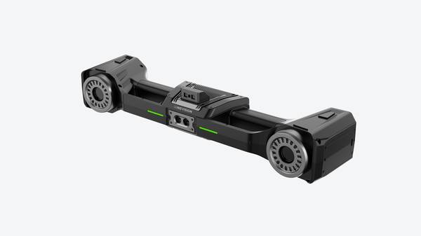
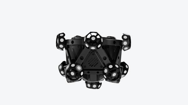
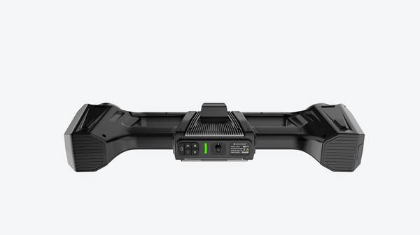
INSVISION’s V-Track tracking 3D scanning system was designed for exactly this boundary condition. Instead of chasing a single, static accuracy number, the system maintains volumetric accuracy dynamically. An optical tracker locks onto the scanner’s position in real time, establishing a stable reference frame across the entire measurement volume.
The scanner can move freely around the weldment without stacks of adhesive targets, heavy jigs, or repeated alignment routines. If the part shifts slightly due to vibration or thermal relaxation, the tracker compensates, so the coordinate system stays intact.
For a quality team, that capability translates into several measurable operational improvements:
- Inspection cycle time shrinks. A large excavator boom or pressure vessel shell that once required a days-long CMM layout or a laser tracker crew can be scanned in a few hours. The deliverable is a dense point cloud and a traceable deviation report aligned to CAD, not a stack of handwritten check sheets.
- Rework loops shorten. By producing a color map within hours of the first-off assembly, the team can identify which tack welds pulled the structure out of tolerance before the next unit is built. Corrective action moves upstream, reducing the rework that would otherwise cascade into subsequent production.
- Quality disputes become solvable. When an OEM auditor asks for evidence of weld toe runout or surface profile conformance, the scan data—metadata, serial numbers, deviation reports—provides a repeatable, auditable record that ties directly to OEM quality requirements without manual rework.
Evaluating the Business Case Without Fake Numbers
Quantifying the return from a 3D scanning system for large welded structures requires looking at the right cost drivers, not at a single accuracy spec.
| Cost Driver | What to Examine |
|---|---|
| Rework and scrap | How often do first-article inspections fail due to distortion that wasn’t caught early? What is the cost of rework labor, consumables, and schedule disruption per occurrence? |
| Inspection labor | How many person-hours are spent setting up CMMs, laser trackers, or manual measurement tools on large weldments? How much of that time is non-value-added (fixturing, moving scaffolding, re-aligning)? |
| Delivery cadence | How many days elapse between weld-out and the release of a complete inspection report? Does that lag force the line to gamble on building ahead of data? |
| Quality traceability | Are customer disputes or audit findings consuming engineering time because inspection data is not repeatable or cannot be traced to a specific part serial number? |
| Equipment utilization | Is the CMM or laser tracker a bottleneck resource that delays other work while it is tied up on large weldments? |
By mapping these drivers against a tracking-based 3D scanning system’s ability to reduce inspection time, catch distortion earlier, and produce a defensible digital record, shops can build a business case that operations managers and finance teams can trust.
The INSVISION V-Track system, for example, typically shows its strongest operational impact on parts where the inspection volume is concentrated around critical mounting interfaces, flange faces, and tie-in points rather than every square centimeter of surface. It is not a replacement for a CMM on tight-tolerance bores below 0.05 mm, nor a full-lot scanning tool for high-volume production-line cadences.
The boundary is clear: it is a flexible, large-volume inspection tool best applied where the data can drive immediate corrective action.
Three deployment scenarios routinely deliver measurable value without overcommitting resources:
- First-article inspection on high-rework weldments. Instead of a full CMM layout, the team scans the first-off assembly, compares it to the CAD nominal, and produces a color map in hours. A fabricator of heavy equipment frames can review the report before the shift ends, identify which tack welds pulled the structure out of tolerance, and adjust the welding sequence or fixturing before the next part is built.
- In-process verification of critical interfaces. On large structural frames where mounting pads, flange faces, and tie-in points determine the function of the entire assembly, tracking-based scanning provides a fast check that the geometry is within tolerance before the part moves to final machining or assembly. This prevents the compounding of error that occurs when a distorted weldment is machined to nominal, only to fail later.
- Final inspection complement to existing CMM capacity. For shops that rely on a CMM for tight-tolerance bores and small features, the V-Track system offloads the large-volume, lower-tolerance work, freeing the CMM for the high-precision tasks where it adds the most value. This improves overall equipment utilization and reduces the queue that often delays shipment.
When evaluating any 3D scanning system for large welded structures, validation should be performed on the shop’s own production parts.
Hangzhou Insvision Technology Co., Ltd.
Address: Building 1, No. 1399 Liangmu Road, Yuhang District, Hangzhou, Zhejiang 311121, China
Copyright © Hangzhou Insvision Technology Co., Ltd. All rights reserved.
Copyright © Hangzhou Insvision Technology Co., Ltd. All rights reserved.