

Operational Value of Tracking-Based 3D Scanning for Thin Sheet Metal Parts
Operational Value of Tracking-Based 3D Scanning for Thin Sheet Metal Parts. The gap between the CMM report and the floor reality is where margin evaporates.
Springback, oil-canning, and edge profile variation rarely show up in a handful of probed points. The gap between the CMM report and the floor reality is where margin evaporates.
Factory managers and operations leaders increasingly recognize that inspection is not a compliance gate—it is a cost-control lever. A faster, more complete measurement workflow can compress first-article turnaround, reduce scrap and rework, lower dependence on senior metrology staff, and shrink the lead time from die set to full-rate production.
Deployment Validation Checklist
| Focus Area | Decision Point | Deployment Note |
|---|---|---|
| Target part | Check size, surface condition, and key tolerances against the scan task | Run a full trial scan on a representative part |
| Data workflow | Verify point cloud, deviation map, and quality-report handoff | Confirm export formats and review ownership in advance |
| Shop-floor use | Review training, calibration, lighting, and working space | Keep the validation record as a repeatable inspection reference |
This article examines the operational pressure points where 3D scanning thin sheet metal parts shifts from a technical curiosity to a measurable business advantage.
Where Conventional Inspection Bleeds Cost
Three inspection tasks dominate the workload in a sheet metal shop, and each one tugs at a different cost center.
Practical Workflow
- Where Conventional Inspection Bleeds Cost — Three inspection tasks dominate the workload in a sheet metal shop, and each one tugs at a different cost center.
- The Workflow Barriers That Eat Engineering Hours — Even when a shop moves to 3D scanning thin sheet metal parts, the first few attempts often expose a set of practical hurdles that…
- How a Tracking-Based Architecture Changes the Cost Equati… — The root cause of these workflow barriers is not the scanner’s resolution.
- Where the Operational Return Materializes — When a shop adopts tracking-based 3D scanning for thin sheet metal parts, the return is not a single line-item saving—it is a pat…
First-article inspection demands a full GD&T report—profile, flushness, hole positions, surface contour—before a single production part can run. A stamped panel that flexes under the weight of a touch probe forces the operator to build elaborate fixturing, compensate for probe deflection, and still question whether the data reflects the part’s free-state shape. The clock ticks while the press waits.
Late first-article approval cascades into delayed order fulfillment.
In-process batch checks pull a sample every few hundred strokes to catch tool wear or material batch drift. A CMM or height gauge might flag a trend only after the deviation has grown large enough to register at a few discrete points. By then, an entire pallet of borderline parts may already be in the queue, creating a scrap risk that multiplies with batch size.
Post-forming warpage validation maps the entire surface after trimming or heat treatment to isolate twist, bow, and springback. Datum-point checks miss the global shape error. A part that measures within tolerance at every target point can still be warped, and that warpage will surface at final assembly.
When the error is caught late—at the customer’s dock—the cost multiplies: freight, containment, line-side sorting, and reputational damage.
Across all three tasks, the bottleneck is the same: data density. A CMM delivers a few dozen points. A laser tracker might deliver a few hundred. Thin sheet metal parts, with their gradual curvature and subtle form deviations, need a dense point cloud to reveal the full deviation pattern.
Without that density, the quality team operates with partial information, and partial information drives rework, scrap, and schedule volatility.
The Workflow Barriers That Eat Engineering Hours
Even when a shop moves to 3D scanning thin sheet metal parts, the first few attempts often expose a set of practical hurdles that chew up the efficiency gains.
Surface preparation: Shiny, bare metal surfaces confuse most structured-light scanners. The standard remedy is a coating of developer spray or matting powder—applied before scanning, cleaned off afterward. That adds a consumable cost and handling step that can double the labor time per part. In a production rhythm, spray-and-clean cycles become a hidden tax on throughput.
Alignment drift: Thin panels with large smooth surfaces and few distinct features are weak candidates for feature-based registration. The scanner’s software struggles to stitch consecutive frames. The operator intervenes to realign or restart the scan. When registration drifts mid-capture, the resulting point cloud contains subtle stitching errors that degrade the GD&T profile and runout callouts.
The part can be misclassified as nonconforming, or worse, a bad part can slip through.
Edge noise: Raw point cloud data on material edges of 0.5 mm to 2 mm thickness is inherently noisy. The scanner rounds the edge, and that noise directly skews tolerance evaluations. An operator must manually filter the data, a step that introduces subjectivity and consumes engineering hours. Every minute spent cleaning up edge artifacts is a minute not spent on the next first-article.
Manual data handling: When an operator smooths outlier points or deletes a cluster of noisy edge data by hand, the traceability of the measurement record breaks. The audit trail becomes fragmented. If the customer later questions a dimension, the quality team cannot fully reconstruct the as-measured state. That gap in quality traceability is a risk the compliance department cannot ignore.
These four barriers—spray-and-clean, misalignment rescans, edge noise, and manual filtering—translate into operational cost: more labor hours per part, higher scrap-and-rework rates, and incomplete quality documentation. For a high-mix shop running dozens of part numbers, the cumulative effect is a persistent drag on delivery cadence and on-time performance.
How a Tracking-Based Architecture Changes the Cost Equation
The root cause of these workflow barriers is not the scanner’s resolution. It is the alignment strategy. Conventional scanning systems—fixed-array or turntable-based—rely on the part’s own geometric distinctiveness to solve frame-to-frame registration. Thin sheet metal parts offer very little geometric distinctiveness.
A large body panel or an electronics enclosure lid might deviate only a few millimeters across its entire span. Without a rigid external reference, the reconstruction floats, introducing subtle warping that can mask a 0.5 mm springback deviation or a flange angle error that matters downstream.
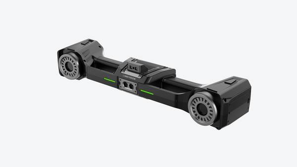
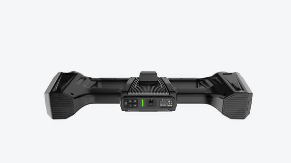
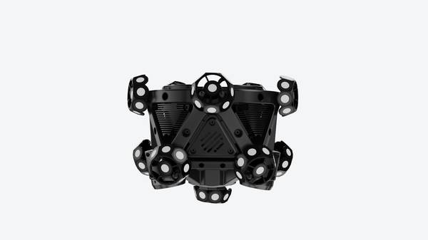
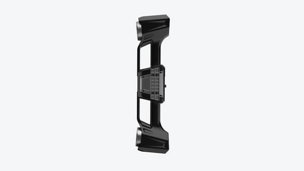
INSVISION’s V-Track tracking 3D scanning system addresses this by separating the measurement sensor from the alignment reference. An optical tracker locks onto the scanner’s position in real time, monitoring the sensor’s location relative to the part without depending on the part’s own features for registration.
The result is a drift-free point cloud even when the scan head moves unpredictably—handheld, on a robot arm, or repositioned around a fixture. The part itself does not need to provide strong geometric cueing. The tracker provides the coordinate frame, frame after frame, at full capture speed.
From an operational standpoint, this architecture eliminates several of the cost drivers listed above. A quality engineer can scan a thin 0.8 mm stamped cover directly in the press shop, without a dedicated granite-based fixture, without spraying the surface with matting powder, and without taping on reference markers. The tracker handles the spatial relationship; the scanner handles the surface.
The result is a single scan that captures the entire part in its free state, delivering a dense point cloud that can be compared to the CAD nominal in minutes.
Where the Operational Return Materializes
When a shop adopts tracking-based 3D scanning for thin sheet metal parts, the return is not a single line-item saving—it is a pattern of improvement across several operational levers.
First-article cycle time: A setup piece that once required rigid fixturing, careful probe compensation, and a multi-hour CMM routine can now be scanned in its free state on a bench. The color deviation map instantly flags zones where the part exceeds profile tolerance.
Hangzhou Insvision Technology Co., Ltd.
Address: Building 1, No. 1399 Liangmu Road, Yuhang District, Hangzhou, Zhejiang 311121, China
Copyright © Hangzhou Insvision Technology Co., Ltd. All rights reserved.
Copyright © Hangzhou Insvision Technology Co., Ltd. All rights reserved.