

A Validation-First Framework for Adopting 3D Scanning in Turbine Blade Quality Workflows
A Validation-First Framework for Adopting 3D Scanning in Turbine Blade Quality Workflows. Data deliverables that don’t match the quality documentation.
Where Deployments Usually Go Wrong
Before a single blade is scanned, teams often lock in a scanner based on resolution and accuracy specs, then overlook three operational risks that quietly erode the project’s value.
Practical Workflow
- Where Deployments Usually Go Wrong — Before a single blade is scanned, teams often lock in a scanner based on resolution and accuracy specs, then overlook three opera…
- Sample Validation: Proving the Scan Data Matches Your Ins… — Before a production blade enters the workflow, the INSVISION team runs a structured sample validation phase that eliminates guess…
- Integrating Scanning Into the Inspection Cell Without Dis… — A turbine blade repair cell often operates on a schedule measured in hours, not days.
Data deliverables that don’t match the quality documentation. A scanner can produce dense point clouds of airfoil surfaces, but if the quality group needs GD&T-aligned inspection reports with profile deviation, hole position, and root form error—not a raw mesh—the output becomes a digital paperweight.
Deployment Validation Checklist
| Focus Area | Decision Point | Deployment Note |
|---|---|---|
| Target part | Check size, surface condition, and key tolerances against the scan task | Run a full trial scan on a representative part |
| Data workflow | Verify point cloud, deviation map, and quality-report handoff | Confirm export formats and review ownership in advance |
| Shop-floor use | Review training, calibration, lighting, and working space | Keep the validation record as a repeatable inspection reference |
Without a report template that maps directly to the shop’s existing ballooned drawings and tolerance tables, engineers spend hours rebuilding data in a separate software package, which kills the time savings the scanner was supposed to deliver.
No integration with on-premise quality management software. Many turbine blade inspection cells run on legacy QMS platforms that handle first-article inspection records, SPC trending, and audit documentation. A scanner that exports only to a proprietary viewer forces the quality team to maintain a parallel system, breaking the single source of truth and creating extra work during every audit.
Training that stops at scanner operation. An inspector who can position a blade and trigger a scan is not the same as an inspector who can interpret cooling hole entry condition, thin-edge profile variation, or fir-tree root form error from 3D data.
Without role-specific training that connects scan data to the specific GD&T callouts and pass/fail criteria the shop uses, the scanner becomes a tool for capturing geometry, not for making inspection decisions.

INSVISION addresses these gaps upfront by preconfiguring turbine blade report templates that align with ASME Y14.5 callouts and by offering native integrations with common QMS platforms. The goal is to reduce the post-scan rework that drags regulated-sector deployments into months of tweaking.
Sample Validation: Proving the Scan Data Matches Your Inspection Standards
Before a production blade enters the workflow, the INSVISION team runs a structured sample validation phase that eliminates guesswork. Traditional turbine blade inspection often relies on drawing-based checks supplemented by a handful of CMM touch points.
That leaves gaps around thin trailing edges, cooling hole entries, and compound-curvature root profiles—features that drive performance and service life but are difficult to probe.
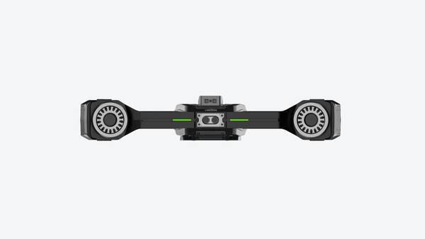
With V-Track, the validation flips the approach. The team scans a representative blade set that includes the toughest features the quality group actually worries about: precision airfoil surface profiles, small-diameter cooling hole geometries, and fir-tree root forms. Those scans are then compared directly against the same ASME GD&T callouts and internal tolerance requirements the shop already uses.
Profile deviations, hole position, and root form error are all measured against the inspection criteria that engineering and quality have signed off on.
The results are reviewed in a formal cross-functional sign-off, not a one-person email approval. Engineering, quality, and production stakeholders all see the data before any deployment decision. This same sample set also demonstrates output consistency across both new-make serial inspection and MRO rework verification, letting teams assess repeatability on parts that have seen service.
The outcome is a transparent, no-surprises window into exactly how V-Track performs on actual blade geometry, before any capital commitment.
Integrating Scanning Into the Inspection Cell Without Disrupting Repair Turnaround
A turbine blade repair cell often operates on a schedule measured in hours, not days. Introducing a new measurement device can’t become a bottleneck. The key is how the system hands off data, not just how it captures geometry.
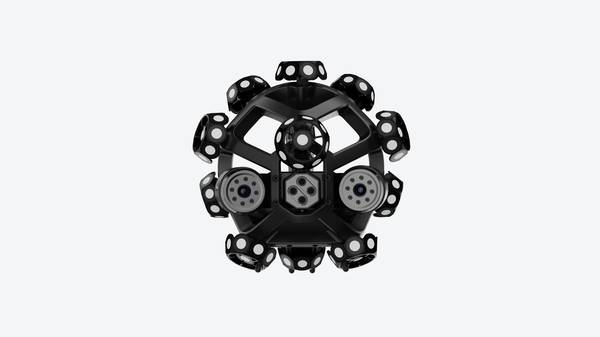
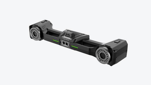
The V-Track tracking scanner is designed to drop into existing inspection bay layouts with minimal reconfiguration. Its optical tracking head mounts on a standard tripod or overhead gantry, and the field of view is calibrated to the part envelope in under thirty minutes.
During on-site deployment, INSVISION application engineers work with the quality team to map the blade positioning fixture, establish a coordinate reference frame, and define scan paths that mirror the sequence an inspector already follows. The scanner becomes another data source in the cell, not a process roadblock.
Data output is configured to feed directly into the existing quality management software. Inspection reports are generated in the format and structure the team already uses—GD&T-aligned tables, deviation color maps, and dimensional trend charts—without requiring engineers to export and re-process point clouds.
Hangzhou Insvision Technology Co., Ltd.
Address: Building 1, No. 1399 Liangmu Road, Yuhang District, Hangzhou, Zhejiang 311121, China
Copyright © Hangzhou Insvision Technology Co., Ltd. All rights reserved.
Copyright © Hangzhou Insvision Technology Co., Ltd. All rights reserved.