

3D Scanning Explained: How Large-Format Handheld Scanners Capture Complex Surfaces
The answer lies in the distinction between single‑frame accuracy and the accumulated error across hundreds of merged frames.
The Optical Principle Behind Structured‑Light Handheld 3D Scanning
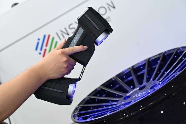
A handheld 3D scanner projects a known pattern of light onto a surface and observes how that pattern deforms. In the case of a multi‑line laser scanner, a series of parallel laser lines are swept across the object. Cameras inside the device triangulate the position of each point along every line by measuring the angle between the projected line and the reflected ray.
When a scanner uses 50 cross‑line blue laser beams, the pattern is denser and the projection is less affected by ambient light, which helps resolve fine features and transitions across edges. The result is a point cloud—a set of coordinates in 3D space—that can be meshed into a digital surface model. This process is fundamentally different from single‑point probing;
it trades point‑by‑point precision for area‑based coverage, but achieving metrology‑grade accuracy requires careful control of exposure, alignment, and volumetric calibration. The scanner must be able to stitch multiple frames together in real time, using either target stickers or the part’s own geometry, without accumulating drift that would ruin the global accuracy.
Deployment Validation Checklist
| Focus Area | Decision Point | Deployment Note |
|---|---|---|
| Target part | Check size, surface condition, and key tolerances against the scan task | Run a full trial scan on a representative part |
| Data workflow | Verify point cloud, deviation map, and quality-report handoff | Confirm export formats and review ownership in advance |
| Shop-floor use | Review training, calibration, lighting, and working space | Keep the validation record as a repeatable inspection reference |
Term Notes
A handheld 3D scanner projects a known pattern of light onto a surface and observes how that pattern deforms.
What Determines Practical Accuracy and Speed on Large P…Factory‑floor users often ask why a scanner rated at 0.020 mm volumetric accuracy can produce a scan that deviates more than…
Where Large‑Format Handheld Scanning Fits and Where It…Large‑format handheld scanners are well‑suited to reverse engineering of castings, sheet metal assemblies, and composite pan…
How INSVISION’s AlphaVista Approaches the Large‑Format…The AlphaVista large‑format handheld scanner by INSVISION is built around the principle of wide‑area, high‑speed capture wit…
What Determines Practical Accuracy and Speed on Large Parts
Factory‑floor users often ask why a scanner rated at 0.020 mm volumetric accuracy can produce a scan that deviates more than that on a full‑size vehicle panel. The answer lies in the distinction between single‑frame accuracy and the accumulated error across hundreds of merged frames. A large‑format handheld scanner addresses this through a combination of wide field of view and high frame rate.
A wider field of view reduces the number of frames needed to cover a large surface, which in turn reduces the number of stitching events and the accumulation of alignment error. A high scan rate—often measured in hundreds of thousands or millions of points per second—keeps the acquisition quick enough to prevent operator fatigue from introducing motion artifacts.
The blue laser wavelength is also relevant: blue light is absorbed less deeply into metallic surfaces than red light, which helps suppress subsurface scattering and improves edge sharpness on semi‑reflective materials.
When scanning a part that is two meters long, the practical deliverable accuracy is a function of frame overlap quality, the stability of the part and the environment, and the software’s ability to perform global bundle adjustment after capture.
Where Large‑Format Handheld Scanning Fits and Where It Does Not
Large‑format handheld scanners are well‑suited to reverse engineering of castings, sheet metal assemblies, and composite panels where the goal is a watertight reference model or a comparison against CAD. They are also used for rapid dimensional inspection of incoming parts, particularly when the alternative is a hard gauge or a time‑consuming CMM fixture setup.
The technology works best on parts larger than about 300 mm in any dimension, where the scanner can be held at a comfortable working distance and the wide field of view minimizes the number of scan passes. It is not the right tool for bore diameters below 5 mm, deep narrow slots, or mirror‑polished surfaces without proper preparation.
On those features, the laser line becomes too wide relative to the feature, or the reflection saturates the sensor, and alternative methods such as a portable CMM with a tactile probe or a dedicated small‑object scanner are more appropriate. The key is to match the scan technology to the feature size and surface condition, not to force every inspection task into one device.
How INSVISION’s AlphaVista Approaches the Large‑Format Challenge
The AlphaVista large‑format handheld scanner by INSVISION is built around the principle of wide‑area, high‑speed capture with 50 cross‑line blue lasers. Its field of view is designed to cover a large patch in one frame, which directly addresses the drift‑accumulation problem on large parts.
The device is integrated with INSVISION’s 3D INSVISION software platform, which handles data processing from alignment to mesh generation in a single environment. For reverse engineering workflows, the combination of wide‑area scanning and the software’s ability to produce clean, de‑noised meshes allows engineers to go from physical part to editable CAD model with fewer intermediate steps.
In practical terms, a quality engineer inspecting a formed panel can hold the 1070‑gram scanner comfortably, capture the entire surface in a few passes, and have a deviation color map ready for review without exporting data to multiple software packages. A common misunderstanding is that a scanner with more laser lines is always better;
the real benefit is that the 50‑line pattern provides enough density to capture compound curvature transitions without missing small fillets or step features. The ergonomic, lightweight design also reduces the operator’s influence on the data, which is a factor often overlooked in metrology‑grade applications.
In summary, a large‑format handheld 3D scanner is not a universal replacement for all inspection tools, but it occupies a specific and growing role where speed, surface coverage, and ease of use on large parts outweigh the need for sub‑micron point accuracy. The technology works because of careful optical and algorithmic design—balancing laser line count, field of view, frame rate, and software compensation.
As the industrial world digitizes more of its physical inventory, understanding these principles helps teams select the right tool for the right job and avoid the all‑too‑common mistake of treating a scanner as a magic camera.
Hangzhou Insvision Technology Co., Ltd.
Address: Building 1, No. 1399 Liangmu Road, Yuhang District, Hangzhou, Zhejiang 311121, China
Copyright © Hangzhou Insvision Technology Co., Ltd. All rights reserved.
Copyright © Hangzhou Insvision Technology Co., Ltd. All rights reserved.