

A Practical Guide to 3D Scanning Methods for Industrial Inspection
Three-dimensional scanning has moved from a niche metrology tool into a standard part of manufacturing quality control, reverse engineering, and digital twin wo
What 3D Scanning Methods Actually Measure
At the most basic level, every industrial 3D scanning method collects a set of spatial coordinates from the surface of a physical object and converts them into a digital representation — typically a point cloud, a mesh, or a parametric CAD model. The difference between methods lies in the physical phenomenon used to range each point.
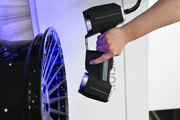
Laser triangulation systems project a laser line or spot onto the surface and observe its position through a camera at a known angle; the displacement of the laser trace reveals the surface height. Structured light scanners replace the laser line with a series of fringe patterns, and by analyzing how those patterns deform across the surface, they compute dense per-pixel depth maps.
Photogrammetry, by contrast, extracts 3D coordinates from multiple overlapping photographs using bundle adjustment, without projecting any active light source.
Deployment Validation Checklist
| Focus Area | Decision Point | Deployment Note |
|---|---|---|
| Target part | Check size, surface condition, and key tolerances against the scan task | Run a full trial scan on a representative part |
| Data workflow | Verify point cloud, deviation map, and quality-report handoff | Confirm export formats and review ownership in advance |
| Shop-floor use | Review training, calibration, lighting, and working space | Keep the validation record as a repeatable inspection reference |
Each technique measures something slightly different: a laser scanner captures the geometric intersection of a plane with the object, a structured light system captures the apparent distortion of a light code, and photogrammetry triangulates feature points from passive images. These differences cascade into every downstream decision about accuracy, speed, and surface compatibility.
Practical Workflow
- What 3D Scanning Methods Actually Measure — At the most basic level, every industrial 3D scanning method collects a set of spatial coordinates from the surface of a physical…
- The Core Optical Principles Behind Industrial 3D Scanning — Laser triangulation works on a straightforward geometric relationship.
- Where Each Method Fits — and Where It Doesn’t — The boundary conditions for each method are not just about the object;
- Automating the Scan: From Manual Metrology to Inline Insp… — When the scanning task moves from a one-off quality check to a repetitive production environment, manual methods hit a wall.
The Core Optical Principles Behind Industrial 3D Scanning
Laser triangulation works on a straightforward geometric relationship. A laser source and a detector are placed at a fixed baseline, and the angle of the returning laser spot maps directly to a distance. The method excels at scanning geometrically complex, deeply recessed areas because the laser plane can cut into cavities that a camera-based fringe projector might not reach.
However, it is sensitive to surface reflectivity and color; highly specular or dark surfaces can scatter the beam away from the detector or absorb it, creating dropouts. Structured light systems take a different approach, often using a digital light processing projector and one or more cameras arranged in a stereo configuration.
The projector casts a sequence of phase-shifted sinusoidal patterns, and the phase unwrapping process yields a dense, high-resolution point cloud. This method is fast and produces very clean data on matte, diffusely reflecting surfaces, but it struggles with transparent, highly reflective, or extremely dark materials.
Photogrammetry is fundamentally passive: it relies on natural or applied target features and the geometry of multiple views. Without a controlled light source, it is inherently less precise on featureless surfaces, but it handles large-scale objects well and can be combined with coded targets to establish a global coordinate system that ties local scans together.
In practice, many industrial workflows combine these methods — for example, using photogrammetry to build a reference frame for a structured light scanner — to cover large volumes while maintaining local detail.
Where Each Method Fits — and Where It Doesn’t
The boundary conditions for each method are not just about the object; they involve the environment, the operator, and the required data deliverable. Laser triangulation can handle ambient light reasonably well and works on a wide range of part sizes, but it is slower when capturing full-field data.
Structured light is ideal for small-to-medium parts with freeform surfaces that need high-density data quickly, but it demands controlled lighting and a stable setup. Photogrammetry is the go-to for large castings, tooling, or aircraft components where no single scanner can cover the entire volume, but it requires significant skill to place and measure targets correctly.
A common mistake is to assume that a scanner with a ten-micron resolution will deliver ten-micron part accuracy. Resolution is the smallest surface feature the system can distinguish; accuracy is the closeness of the measured point to the true geometry, and it depends on calibration, thermal stability, part fixturing, and the reference scale.
For metrology-grade inspection, the system must be traceable to a length standard, and the software must support geometric dimensioning and tolerancing analysis rather than just a color map of deviations.
Similarly, scan speed must be understood in terms of real duty cycles: a scanner that captures a million points per second may still require multiple setup changes and marker applications, which dominate the total inspection time on a production floor.
Automating the Scan: From Manual Metrology to Inline Inspection
When the scanning task moves from a one-off quality check to a repetitive production environment, manual methods hit a wall. Automated 3D scanning systems address this by integrating the sensor, part handling, and analysis into a single workflow. The AlphaAutoScan-400 from INSVISION, an ISO 9001:2015 certified manufacturer, is designed specifically for such scenarios.
It combines structured light and AI-driven algorithms to perform automated inspection of small-to-medium industrial parts, with a focus on micron-level surface defect recognition on complex curved geometries. Rather than relying on an operator to position the part and interpret a deviation map, the system uses a predefined inspection routine with millisecond-level response suitable for dynamic production lines.
The accompanying software, 3D INSVISION, consolidates scanning, alignment, comparison, and model generation in one environment, while SMARPARA Q adds PTB-certified GD&T tools and supports multi-source data alignment for full traceability.
Hangzhou Insvision Technology Co., Ltd.
Address: Building 1, No. 1399 Liangmu Road, Yuhang District, Hangzhou, Zhejiang 311121, China
Copyright © Hangzhou Insvision Technology Co., Ltd. All rights reserved.
Copyright © Hangzhou Insvision Technology Co., Ltd. All rights reserved.