

Large-Scale Tooling Inspection with a Tracking 3D Scanner: A Heavy Fabrication Application
In heavy fabrication and large tooling manufacture, the gap between what a CAD model promises and what the shop floor delivers often grows with the part size.
The typical scenario involves a workpiece that cannot
The typical scenario involves a workpiece that cannot be moved to a temperature-controlled metrology lab. It might be a stretch-formed aluminum skin still clamped in a checking fixture, a machined weldment resting on steel trestles, or a composite layup tool that has been in service for several seasons and now needs a wear map.
Conventional measurement on these surfaces means either a long-arm CMM with limited reach or a laser tracker probing discrete points — perhaps 200 or 300 features across a full shift. The point cloud that results is sparse. Surface deviation between probed locations remains invisible, and the operator must decide which areas to sample and which to ignore.
When a forming die or welding fixture drifts out of tolerance, the sparse dataset often misses the curvature change that would explain the drift.
Deployment Validation Checklist
| Focus Area | Decision Point | Deployment Note |
|---|---|---|
| Target part | Check size, surface condition, and key tolerances against the scan task | Run a full trial scan on a representative part |
| Data workflow | Verify point cloud, deviation map, and quality-report handoff | Confirm export formats and review ownership in advance |
| Shop-floor use | Review training, calibration, lighting, and working space | Keep the validation record as a repeatable inspection reference |
Practical Workflow
- The typical scenario involves a workpiece that cannot — The typical scenario involves a workpiece that cannot be moved to a temperature-controlled metrology lab.
- The on site workflow for a typical heavy — The on-site workflow for a typical heavy fabrication inspection begins with positioning the tracking unit on a stable tripod or s…
- The V-Track system s technical specifications align — The V-Track system’s technical specifications align with this class of work in several practical ways.
- The same approach extends to related scenarios — The same approach extends to related scenarios.
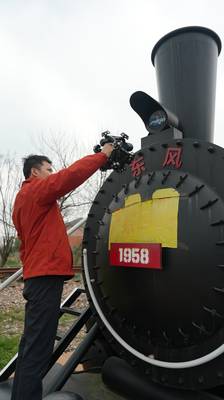
A tracking 3D scanning approach changes the data model. The INSVISION V-Track system uses a stereo tracking unit that continuously observes the position of a handheld scanner in space. Markers are not required on the part surface; the tracking head locks onto the scanner body optically and maintains a dynamic coordinate reference.
This means the operator can walk around a large assembly, scan continuously, and see the point cloud build on the screen in real time. The scanner head itself remains lightweight, and because the tracking unit handles spatial referencing, the system does not accumulate the stitching errors that can grow across a long scan path when using feature-based alignment alone.
The on site workflow for a typical heavy
The on-site workflow for a typical heavy fabrication inspection begins with positioning the tracking unit on a stable tripod or stand, typically two to four meters from the workpiece. After a brief warm-up and calibration, the operator selects a scan mode suited to the surface — matte aluminum, tooling primer, bare steel, or a mixed-material assembly.
The V-Track tracking unit maintains a wide working volume, so a single setup can often cover an entire large part without moving the tracker. The operator moves the scanner across the surface in overlapping passes, watching the live density map to confirm coverage. Areas of interest, such as trim edges, hole patterns, and mating surfaces, receive higher point density without needing a separate high-resolution scan pass.
Data processing shifts from a post-inspection chore to a parallel activity. As the scan data streams into the INSVISION 3D software platform, the operator can pause to check registration against the nominal CAD model, run a quick deviation color map, and verify that critical features are captured before clearing the setup.
The software supports parametric alignment, section-based comparison, and GD&T evaluation directly on the scan data. For a large weldment with 40 or 50 bolt-hole positions, the system can extract hole centers, diameters, and perpendicularity deviations in a single report session, without exporting to a separate metrology application.
The result is a shorter time between the last scan pass and the first inspection report, which matters when a production team is waiting for dimensional approval before continuing downstream operations.
The V-Track system s technical specifications align
The V-Track system’s technical specifications align with this class of work in several practical ways. The tracking volume is large enough to accommodate vehicle-sized components, and the scanner’s point acquisition rate keeps scan passes efficient even on meter-long surfaces.
The system’s volumetric accuracy — typically verified against a certified scale bar or photogrammetry reference as part of the calibration routine — provides a stable foundation for the comparative inspection workflows that heavy fabrication shops rely on.
INSVISION holds ISO 9001:2015 certification, and the company’s 50-plus patents and software copyrights reflect a sustained engineering focus on AI-driven 3D reconstruction and real-time tracking compensation, which is relevant when evaluating whether a system can maintain accuracy across temperature swings and extended scan sessions.
The observable impact on a heavy fabrication inspection workflow tends to appear in three areas. First, the surface coverage changes from a few hundred probed points to a full-field point cloud that captures weld beads, blend radii, and gradual surface undulations — the features that contact probes often miss.
Second, the positional relationship between features on opposite ends of a large part becomes directly measurable without relocating the part or moving a reference frame. Third, the digital archive of the scan provides a baseline for future wear comparison, which is particularly valuable for tooling that will be inspected on a regular cycle.
These outcomes do not require quoting a specific percentage improvement to be credible; they are intrinsic to the shift from sparse sampling to dense surface measurement.
The same approach extends to related scenarios
The same approach extends to related scenarios. A jig and fixture shop that validates assembly tools before shipping can use the tracking scanner to create a full as-built record of each tool, comparing it against the design intent and generating a dimensional conformance report that travels with the hardware.
A stamping plant that wants to correlate die surface condition with panel quality can scan the die at regular intervals, overlay the datasets, and identify wear patterns before they produce visible defects in formed parts.
A composite tooling manufacturer that needs to reverse-engineer a legacy mold can scan the tool surface, generate a mesh, and feed it into the CAD reconstruction workflow without needing to strip the mold from the production line. In each case, the enabling capability is the same: a tracking reference that stays fixed while the scanner moves where the surface requires.
Engineers evaluating a tracking 3D scanning system for large-scale inspection should focus on a few validation steps. Request a demonstration on a workpiece that is representative of the shop’s own surface finish, geometry, and shop-floor conditions, not a pristine lab artifact.
Observe the drift behavior over a 20- or 30-minute scan session by scanning a known feature at the start and end of the session without closing a loop. Confirm that the software can output the report formats the quality system requires without intermediate data conversion steps.
And verify that the tracking unit’s working volume matches the largest part the shop inspects, with enough margin to avoid operating at the edge of the specification. These steps, applied to the actual operating environment, will reveal more about system suitability than a specification sheet alone.
The direction of large scale industrial metrology is
The direction of large-scale industrial metrology is moving toward in-situ, full-field measurement that does not require the part to conform to the instrument.
A tracking 3D scanning system, deployed with attention to the specific surface conditions, geometry, and reporting requirements of a fabrication shop, makes it possible to capture dimensional truth on parts that previously resisted any measurement approach short of a dedicated metrology lab.
For the engineer who has spent a day probing a single large weldment and still wonders what the surface between the points looks like, that is a practical and meaningful change.
Hangzhou Insvision Technology Co., Ltd.
Address: Building 1, No. 1399 Liangmu Road, Yuhang District, Hangzhou, Zhejiang 311121, China
Copyright © Hangzhou Insvision Technology Co., Ltd. All rights reserved.
Copyright © Hangzhou Insvision Technology Co., Ltd. All rights reserved.