

What Moldmakers Learn When They Stop Treating Every Cavity the Same Way
Mold inspection has always been a balancing act between speed and certainty. In a busy toolroom, a complex multi-cavity mold may sit on a surface plate for hour
The Geometry That Defeats Sparse Sampling
Industrial molds throw a wide range of geometric challenges at any inspection tool. A single mold base can contain deep ribs, narrow slots, organic freeform surfaces, and sharp edges that define the final part. Optical 3D scanning does not mind if a surface is contoured or prismatic, but the real difficulty comes from how those features interact with light.
A polished core insert with a mirror finish reflects blue laser light away from the sensor, creating data dropouts. A textured cavity may scatter the line enough to generate noise. Meanwhile, a deep pocket with a draft angle of less than one degree can be almost invisible to a fixed scanner, and the true bottom of a blind hole is often missed entirely.
Deployment Validation Checklist
| Focus Area | Decision Point | Deployment Note |
|---|---|---|
| Target part | Check size, surface condition, and key tolerances against the scan task | Run a full trial scan on a representative part |
| Data workflow | Verify point cloud, deviation map, and quality-report handoff | Confirm export formats and review ownership in advance |
| Shop-floor use | Review training, calibration, lighting, and working space | Keep the validation record as a repeatable inspection reference |
Scenario Snapshot
A practical way to read the article is through this scenario:
- The Geometry That Defeats Sparse Sampling: Industrial molds throw a wide range of geometric challenges at any inspection tool.
- When Surface Finish Becomes a Measurement Variable: A common blind spot in mold inspection is treating surface finish as a separate concern from dimensional accuracy.
- Building a Workflow Around the Full Data Set: A one-off scan is useful for troubleshooting, but the real value comes when mold inspection is treated as a repeat…
What makes the AlphaScan approach different is not a single magic setting but a capture strategy that accepts these realities upfront. Instead of expecting a flawless first pass, a mold inspector scans the cavity with a deliberate overlap, tilting the scanner to catch steep walls and using the scanner’s ability to maintain tracking on shiny surfaces where a less capable device would lose its reference.
The goal is to gather a dense, continuous point cloud even where the surface is optically difficult, and to do it without spraying the entire mold with developer powder — a step that adds time and can mask the very surface finish defects the inspection is meant to find.
When Surface Finish Becomes a Measurement Variable
A common blind spot in mold inspection is treating surface finish as a separate concern from dimensional accuracy. On a parting line face, a few microns of tool wear or polishing relief can appear as a form error in a CAD comparison, but the cause is surface finish, not dimensional drift.
A handheld scanner like AlphaScan captures enough resolution to show the texture gradient, which allows a metrologist to separate a true wall shift from a polishing artifact. This is especially important for molds that produce transparent or high-gloss parts, where surface waviness directly transfers to the molded component.
Deep cavities and thin standing walls introduce another layer of complexity. A tall core pin can flex under clamping pressure or thermal load, and the distortion is rarely uniform from root to tip. Because the AlphaScan collects full-field data, it can map the taper of a pin across its entire length rather than sampling only the top and bottom.
In the 3D INSVISION software environment, the scanned data is registered to the CAD model, and a color map instantly reveals whether the pin is straight, tapered, or bowed. This kind of visualization makes it practical to discuss remachining decisions with the toolroom floor without a long chain of emails and misinterpreted 2D drawings.
Building a Workflow Around the Full Data Set
A one-off scan is useful for troubleshooting, but the real value comes when mold inspection is treated as a repeatable process. The typical sequence starts with setting a reference frame.
For a mold without a CAD model of the current cavity state, a known-good cavity or a master insert can be scanned and used as the benchmark — the same principle INSVISION has applied in cold rolling roll inspection, where a physical reference replaces a digital model.
When a CAD model is available, the alignment is performed directly in SMARPARA Q, which includes GD&T tools for evaluating profile, flatness, parallelism, and position tolerances according to the drawing.
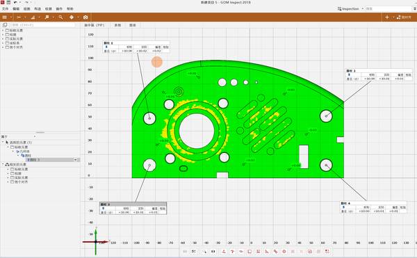
Once aligned, the software overlays the scan data onto the nominal geometry. The inspector can section through the mold at any plane, isolating a gate area, an ejector pin land, or a critical shutoff surface. Deviations are color-coded, and out-of-tolerance zones are flagged.
Rather than exporting a generic pass/fail stamp, the report can include screenshots of the specific areas that need attention, annotated with the deviation values and the tolerance band. This turns the inspection report from a gatekeeper into a working document that the milling department, the EDM operator, and the polisher can all read and act on.
After rework, the same cavity is rescanned, and the new data set is compared against the same reference, closing the loop with a documented before-and-after record.
Where Handheld 3D Scanning Fits in the Mold Lifecycle
The phrase “handheld metrology” can raise eyebrows in a mold shop accustomed to granite tables and climate-controlled CMM rooms. But the AlphaScan was designed around the fact that production molds are not always clean, static, or easy to move. A scan can happen on the press, right after ejection, with the mold still warm. This is not a compromise;
it is a deliberate choice to capture the mold in its working state, when thermal expansion and clamping forces are real. The data reflects the cavity the polymer actually sees, not the cavity as measured on a bench at 20°C.
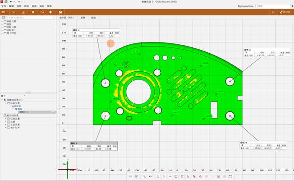
For moldmakers who maintain multiple identical cavities in a single tool, the scanner can digitize each cavity and compare them against each other, quickly identifying which cavity is wearing faster or filling differently. For repair and revision work, the scanner captures the actual geometry before metal is cut, so the new insert is designed to fit the existing cavity, not the other way around.
This reverse-engineering loop, supported by the SMARPARA Q software, compresses the time from a worn mold to a fitted replacement insert. Across all these scenarios, the scanner stays the same; the difference is in how the data is used, not in the hardware itself. That flexibility is what makes a 3D scanning approach hold up under the varied demands of mold inspection, from first article runoff to end-of-life assessment.
Hangzhou Insvision Technology Co.,Ltd.
Address: Building 1, No. 1399 Liangmu Road, Yuhang District, Hangzhou, Zhejiang 311121, China