

What Makes reverse engineering 3D scanning for motorc Difficult to Capture Accurately
A motorcycle fairing or fender looks simple from a distance, but anyone who has tried to capture its geometry for reverse engineering knows otherwise. The part
The Object Profile: Glossy Paint, Deep Draws, and Part Distortion
Motorcycle exterior parts are typically injection-molded ABS or polypropylene, painted with high-gloss clear coats, and reinforced with ribs and bosses on the back side. The front surface is what matters for aerodynamic fit and styling, but the rear geometry carries the mounting points that align the part to the frame.
A typical side fairing can span 800 mm or more, with wall thicknesses under 2 mm, making it floppy when unclamped. The combination of glossy black or metallic paints and thin sections creates a challenging measurement scenario: the scanner must reject false reflections while still resolving the subtle surface flow that defines the motorcycle’s character lines.
Deep recesses around the headlight bucket and the narrow slots for air intakes introduce shadowing, and the part’s flexibility means it can shift shape between the moment you scan it and the moment you fixture it for inspection.
Deployment Validation Checklist
| Focus Area | Decision Point | Deployment Note |
|---|---|---|
| Target part | Check size, surface condition, and key tolerances against the scan task | Run a full trial scan on a representative part |
| Data workflow | Verify point cloud, deviation map, and quality-report handoff | Confirm export formats and review ownership in advance |
| Shop-floor use | Review training, calibration, lighting, and working space | Keep the validation record as a repeatable inspection reference |
Scenario Snapshot
A practical way to read the article is through this scenario:
- The Object Profile: Glossy Paint, Deep Draws, and P…: Motorcycle exterior parts are typically injection-molded ABS or polypropylene, painted with high-gloss clear coats…
- Why Traditional Tools Miss the Mark on Reflective a…: A coordinate measuring machine (CMM) can pick up a few datum points and some surface profiles, but it cannot dense…
- Designing a Scanning Routine for Accurate Reverse E…: A successful reverse engineering workflow starts with the part’s own geometry dictating the scan path.
These physical traits translate directly into a list of scanning risks. Glossy black surfaces cause laser speckle noise or structured-light dropouts. Thin cantilevered sections vibrate during handling, blurring sharp edges. Large, smooth body panels lack the discrete features that tracking algorithms rely on, so the scanner can lose registration if you move too fast or if the ambient light changes.
The mounting bosses on the back side are often deep inside a ribbed cavity, requiring a small-standoff scanner head to get line-of-sight without crashing into the part. If you ignore these factors, the resulting mesh will be noisy where it should be quiet, and missing exactly where the CAD modeler needs continuity.
Why Traditional Tools Miss the Mark on Reflective and Flexible Surfaces
A coordinate measuring machine (CMM) can pick up a few datum points and some surface profiles, but it cannot densely sample the flowing surface of a fairing without taking days of programming and touch time. The part also has to be rigidly clamped, which introduces a deformed shape that does not match the free-state condition of the part mounted on the bike.
Laser trackers combined with handheld probes solve some of the flexibility issue, but they still rely on reflective targets and struggle with the high gloss unless the surface is sprayed with a temporary matting agent. The operator ends up spending more time prepping and cleaning the part than actually measuring it.
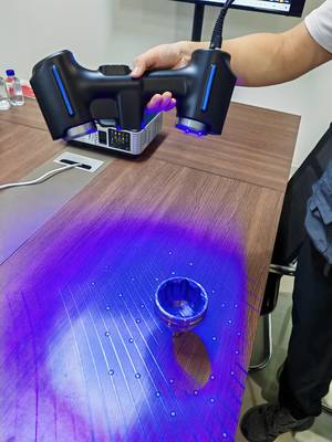
Structured-light 3D scanning takes a different approach. A scanner like the AlphaScan projects a dense blue-light pattern onto the surface and captures the distorted fringes to reconstruct the shape, independent of the part’s color or gloss within a wide working range. The high dynamic range of the cameras allows it to hold detail on black metallic paint and bright chrome accents in the same scan pass.
Because the scan head is handheld, you can walk around the part, orient it freely, and scan the inside of lips and the underside of flanges without building complex fixtures. The part can rest on a soft support in its natural state, and the scanner registers the geometry based on the surface shape itself, not on the stability of a fixture.
For a motorcycle fairing, this means you can capture the full exterior in a few minutes, then flip the part and scan the interior ribs and bosses, and the software will automatically align the two sides into a single coordinate system.
Designing a Scanning Routine for Accurate Reverse Engineering
A successful reverse engineering workflow starts with the part’s own geometry dictating the scan path. For a large fairing with minimal texture, you need to place a few adhesive reference markers on the part or the surrounding table to create a stable tracking frame. The scanner’s software then uses these markers along with the natural surface features to stitch the frames together.
You begin by scanning the large, feature-poor areas first—the side panels—while the scanner builds a global registration. The operator moves in smooth, overlapping passes, keeping the scanner at a consistent standoff distance. If the part is particularly glossy, no powder or spray is needed;
the scanner’s exposure settings can be adjusted on the fly, and the software’s reflection filtering algorithms suppress the hot spots that would otherwise create false peaks.
Deep pockets around the headlight and the narrow gills on the lower cowling require a different scanning angle. The operator tilts the scanner to let the pattern project into the cavity, and the data acquisition software shows a live preview of missing areas, so you can re-scan specific zones until the mesh is watertight.
The thin edges of the fairing are prone to deformation, so the scan strategy includes capturing the part in multiple orientations—face up, then face down resting on a soft cradle—and the software aligns all scans using the reference markers that remain visible.
The result is a complete 3D mesh that captures the outer surface, the inner ribs, the screw bosses, and the sharp edge where the two halves of the mold created a parting line.
From Point Cloud to Production-Ready CAD Model
The raw scan data is a dense mesh of triangles, often with small holes, surface noise, and overlapping layers from the multiple scan orientations. The first step in data processing is global registration and optimization, where the software bundles all the individual frames and minimizes the positional error across the entire dataset.
Next, the mesh goes through a smoothing pass that removes high-frequency noise while preserving the sharp creases and the subtle curvature of the styling surfaces. The software can fill small holes by interpolating the surrounding geometry, but for critical mounting features, the operator will re-scan those areas rather than rely on interpolation.
Once the mesh is clean and watertight, it is imported into a CAD environment for reverse engineering. The designer can extract the main surface patches by fitting NURBS surfaces over the mesh sections, using the scan as a reference for the curvature and the boundary edges. The mounting bosses and screw holes are reconstructed as parametric cylinders and planes, and the ribbing is rebuilt as extruded features.
A quality check is then performed by comparing the reconstructed CAD model back to the original scan mesh, generating a color deviation map that shows exactly where the CAD deviates from the physical part.
For a motorcycle fairing, the tolerance is typically held to within 0.3 mm over the general surface and 0.1 mm around the mounting points, ensuring that the reverse-engineered part will fit the bike without binding or gapping. INSVISION’s AlphaScan, backed by the company’s ISO 9001 and ISO 14001 certifications and its presence in over 20 countries, provides the measurement reliability that such workflows demand.
The scanner’s ability to handle the full range of materials—from matte black polymers to chrome-finished accents—allows shops to standardize on a single device for all their motorcycle exterior parts, eliminating the need for multiple measurement systems and the associated data-merge headaches.
Hangzhou Insvision Technology Co.,Ltd.
Address: Building 1, No. 1399 Liangmu Road, Yuhang District, Hangzhou, Zhejiang 311121, China