

Closing the Loop on Pump Housing Quality with 3D Inspection
When a centrifugal pump housing comes off the machining line, the quality team is rarely just checking a single dimension. They are verifying whether the volute
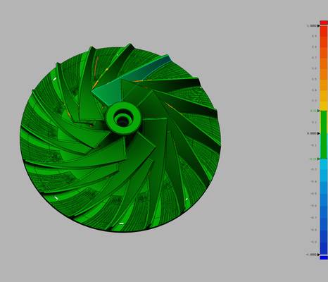
The inspection difficulty starts with the part itself. A typical pump housing is not a prismatic block. It has a spiral volute passage, a suction eye, a discharge flange, a stuffing box bore, and an array of drilled and tapped holes — all distributed across curved external walls that are often only 3 to 8 millimeters thick.
The material is usually cast iron, ductile iron, or stainless steel, and the as-cast surfaces can be dark, slightly rough, or coated with a thin preservative. Machined areas — flange faces, register bores, seal chambers — are frequently shiny and susceptible to ambient reflections.
Deployment Validation Checklist
| Focus Area | Decision Point | Deployment Note |
|---|---|---|
| Target part | Check size, surface condition, and key tolerances against the scan task | Run a full trial scan on a representative part |
| Data workflow | Verify point cloud, deviation map, and quality-report handoff | Confirm export formats and review ownership in advance |
| Shop-floor use | Review training, calibration, lighting, and working space | Keep the validation record as a repeatable inspection reference |
Dimensional tolerances on the seal bore and bearing housing might run to IT6 or IT7, while the volute cut-water clearance is sometimes specified as a profile tolerance of 0.15 millimeters or less. Traditional inspection tends to sample a few cross-sections and feature locations, leaving large portions of the volute surface unverified.
That blind spot matters because local deviations in the volute contour directly affect hydraulic efficiency and noise.
How Pump Housing Geometry Defeats Conventional Measurement
The first problem is access. The volute passage wraps around the impeller cavity, creating a narrow, curved channel that is difficult to reach with a touch probe or a fixed CMM stylus. Deep inside the discharge throat and the suction flange, the line-of-sight constraints of confocal sensors or laser trackers become acute. The second problem is datum transfer.
The primary functional datums — the seal face, the bearing bore, and the mounting feet — are on different planes, often separated by hundreds of millimeters. Aligning the part on a CMM requires multiple setups and sophisticated fixturing. The third problem is the sheer number of features.
A single pump housing may contain over 100 individual inspection characteristics, including position tolerances for threaded holes, flatness of flange faces, concentricity of the seal chamber to the bearing bore, and wall thickness at critical sections. Measuring these with a hard gauge or a CMM demands a large inspection plan, frequent probe changes, and a lot of operator time — often 45 to 90 minutes per part.
Scenario Snapshot
A practical way to read the article is through this scenario:
- How Pump Housing Geometry Defeats Conventional Meas…: The first problem is access.
- Building a Capture Strategy Around the Volute: A practical 3D scanning workflow for pump housings starts with a quick pre-scan assessment.
- From CAD Comparison to a Closed Inspection Loop: The output of a 3D scan is not just a pass/fail report.
Surface finish adds another layer. As-cast volute surfaces are optically cooperative for structured-light scanning, but machined seal faces are bright and can produce specular reflections. The INSVISION AlphaScan handles this mix with adaptive exposure and blue laser technology, which suppresses ambient interference and captures shiny surfaces without spraying the part with developer.
That is a meaningful detail in a production environment, because applying and cleaning powder adds labor and introduces a variable film thickness that can shift the measured surface by a few microns. For a pump housing where the seal face flatness tolerance is 0.02 millimeters, that shift is not negligible.
Building a Capture Strategy Around the Volute
A practical 3D scanning workflow for pump housings starts with a quick pre-scan assessment. The operator checks the part for loose debris, places it on a stable work surface, and determines whether the internal volute needs a specific approach angle. Because the AlphaScan is handheld, the operator can move around the casting, tilting the scanner to look into the suction and discharge openings.
The scan strategy usually follows a simple rule: capture the external envelope first, then go back for the internal features. The external surfaces — mounting feet, flange faces, ribbing — provide a strong geometric reference that the software uses to stitch the internal volute data into the same coordinate system.
For the internal volute, the operator moves the scanner in a slow, steady arc through the throat opening, allowing the live point cloud to build up on the screen. The critical region is the cut-water, where the volute tongue meets the discharge passage. Even a small casting shift or machining error here can create a sharp step that disrupts flow and accelerates wear.
The scanner captures the full 3D profile of this region in one continuous pass, generating a dense point cloud that reveals whether the cut-water radius is consistent and whether the transition is smooth. The entire housing — external and internal — typically takes 8 to 15 minutes to scan, depending on size and access.
The data from the AlphaScan lands in the processing software as a high-resolution mesh. The software aligns the measured mesh to the nominal CAD model using a best-fit or datum-based registration. The engineer then runs a surface comparison, which generates a color map showing deviations across every surface. Regions that are within tolerance appear green; areas approaching the limit appear yellow;
out-of-tolerance zones appear red. The same comparison can be sliced into wall thickness maps, cross-section profiles, and GD&T callouts for individual features. Because the entire surface is captured, the inspection report is not limited to the 20 or 30 points a CMM would measure — it covers the whole part.
From CAD Comparison to a Closed Inspection Loop
The output of a 3D scan is not just a pass/fail report. The real value comes from feeding the data back into the manufacturing process. If the color map shows a systematic deviation on the volute cut-water across multiple housings from the same pattern, the foundry can adjust the core or the machining fixture. If the seal face shows a consistent tilt, the machining setup can be corrected.
The inspection report becomes a process diagnostic tool rather than a final gate.
A typical report for a pump housing includes a part-level surface comparison, a wall thickness analysis with cross-section views at critical planes, and a tabular summary of GD&T results. The AlphaScan software exports these reports in standard formats that can be archived in a quality management system or shared with customers as part of a first-article inspection package.
The combination of full-field data and traceable documentation meets the requirements of ISO 9001 quality management systems, and the measurement accuracy is backed by INSVISION’s certifications including CE, FCC, and CNAS L2865. For manufacturers that ship pump housings to end users who demand dimensional conformance data, the report is a deliverable in itself.
The inspection loop closes when the same scanning setup is used for periodic process checks. Instead of waiting for a CMM to become available, the operator scans one housing per shift, overlays the results with the previous scans, and watches for drift. Any trend toward an out-of-tolerance condition triggers a corrective action before nonconforming parts accumulate.
This shifts the role of inspection from a reactive sorting operation to a proactive control function — and that is where the biggest cost savings often hide.
What Makes 3D Scanning Work for Pump Housing Inspection
The factors that make a handheld 3D scanner effective on pump housings are not theoretical. The part is geometrically complex, optically mixed, and functionally critical.
A scanner that works well on this kind of part needs to handle shiny machined surfaces and dark cast surfaces without constant recalibration, capture deep internal features without external tracking, and deliver data that can be processed into actionable reports in minutes rather than hours. The INSVISION AlphaScan was designed for exactly this class of industrial work.
Its lightweight form factor, rapid point cloud acquisition, and software workflow that connects scan data directly to CAD comparison and report generation make it a practical tool for quality departments that deal with pump housings, valve bodies, compressor casings, and similar fluid-handling components on a daily basis.
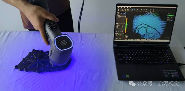
For manufacturers evaluating 3D inspection for pump components, the decision should be tested against the hardest part in the product line — not the simplest. Scan a housing with a deep internal volute, a tight cut-water, and a mix of as-cast and machined surfaces. Check whether the scanner captures the full internal passage without a mirror or a rotary table.
Verify that the software can perform the specific GD&T evaluations required by the engineering drawing. When those checks pass, the scanner becomes not just a measurement device but a permanent part of the quality infrastructure.
Hangzhou Insvision Technology Co.,Ltd.
Address: Building 1, No. 1399 Liangmu Road, Yuhang District, Hangzhou, Zhejiang 311121, China