

Small Precision Part 3D Scanning
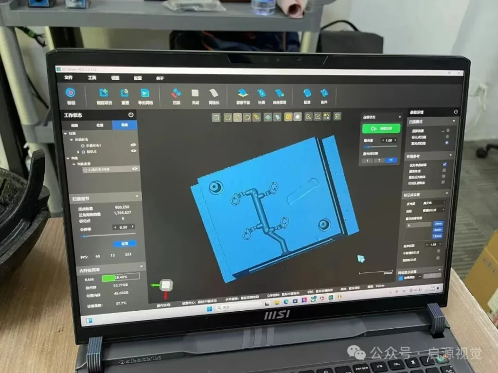
Small precision part 3D scanning is a specialized subset of industrial 3D metrology focused on capturing high accuracy, high resolution three dimensional data of small, tight tolerance manufactured components.
Definition
Small precision part 3D scanning is a specialized subset of industrial 3D metrology focused on capturing high-accuracy, high-resolution three-dimensional data of small, tight-tolerance manufactured components. The workflow is optimized to capture fine surface features and dimensional measurements with repeatable, traceable accuracy, supporting core industrial applications including quality control, first article inspection, reverse engineering, wear analysis, and assembly tolerance validation. It is widely deployed across sectors including precision machining, aerospace component manufacturing, automotive parts production, medical device fabrication, and mold and die inspection.
How It Works
Small precision part 3D scanning relies on non-contact optical measurement principles to capture 3D dimensional data, with workflows varying by technology type:
- Pre-scan preparation: Parts are cleaned of debris, oils, or surface contaminants. For highly reflective, transparent, or dark surfaces, optional matte spraying may be applied to reduce glare and improve data capture, though many modern systems minimize this requirement via adaptive exposure settings. For marker-based workflows, temporary reference markers may be applied to the part or surrounding fixture to enable frame alignment.
- Data capture: Common technology configurations include:
- Structured light systems: Project a sequence of coded visible or blue light patterns onto the part surface. One or more high-resolution cameras capture the deformation of these patterns as they conform to the part’s geometry, and triangulation algorithms calculate 3D coordinates for every point in the field of view.
- Handheld 3D scanners: Use either laser line arrays or compact structured light projectors to capture data, with position registration handled via either on-part reference markers or external optical tracking systems that monitor the scanner’s position in 3D space.
- Automated scanning systems: Integrate structured light or laser scanners with robotic arms, rotary stages, or conveyor systems to pre-program scan paths, capturing all required part angles without manual operator input.
- Post-processing: Raw scan data is processed to remove noise, align overlapping scan frames, and merge data into a unified point cloud or polygon mesh. For metrology applications, the processed data may be compared to a reference CAD model to generate dimensional deviation reports, or exported for reverse engineering to generate a usable CAD file.
Key Parameters and Criteria
Performance of small precision part 3D scanning systems depends on part size, material, environmental conditions, workflow configuration, and software settings. Core parameters used to evaluate system suitability for a given application include the following:
| Parameter | Meaning | Judgment Method |
|---|---|---|
| Measurement Accuracy | Maximum allowable deviation between scanned dimensional values and traceable metrology reference standards | Compare scan measurements of a calibrated artifact (e.g., gauge block, step gauge) to its certified values across multiple scan orientations and positions |
| Point Cloud Resolution (Point Spacing) | Average distance between adjacent 3D data points in the captured dataset, which determines the level of fine surface detail that can be rendered | Calculate the mean distance between neighboring points in a flat, uniform region of a calibrated test artifact, verified via integrated scanner software metrics |
| Minimum Detectable Feature Size | Smallest discrete surface feature (e.g., notch, rib, hole, edge radius) that can be reliably captured and measured with consistent repeatability | Scan a certified test artifact with graded, calibrated feature sizes, and identify the smallest feature that produces dimensional measurements within the system’s stated accuracy range |
| Registration Error | Deviation between overlapping scan frames when aligned to form a single unified 3D dataset | Measure the average deviation at common reference markers or overlapping surface regions across multiple independent scan passes of the same part |
| Material Compatibility Threshold | Range of part surface properties (reflectivity, transparency, color, matte finish) the system can scan without extensive pre-treatment (e.g., matte spraying) | Scan test coupons of common industrial materials (e.g., polished aluminum, clear engineering plastic, black rubber) under standard operating conditions, and assess data completeness and noise levels |
Suitable and Unsuitable Scenarios
Suitable Scenarios
- Incoming quality inspection of small machined, investment cast, injection molded, or 3D printed precision parts
- First Article Inspection (FAI) and Production Part Approval Process (PPAP) documentation for tight-tolerance small components
- Reverse engineering of legacy small precision parts with no existing CAD or design documentation
- Dimensional validation of small tooling, dies, and mold inserts to assess wear or manufacturing deviations
- Assembly tolerance verification for small sub-assemblies with critical fit requirements
- Comparative analysis of as-manufactured parts to original design specifications
Unsuitable Scenarios
- Ultra-precision applications requiring reliable capture of surface features smaller than 2mm
- Inspection of internal holes or cavities with diameters smaller than 5mm, which are inaccessible to non-contact optical scanning
- Dental-specific part scanning, which requires specialized intraoral scanning equipment
- Consumer-grade facial or full-body scanning for non-industrial applications (e.g., content creation, personal modeling)
- Medical diagnostic imaging, which is subject to specialized clinical regulatory requirements not met by industrial scanning systems
- Ultra-micro component manufacturing applications for jewelry or microelectronics, which require nanometer-scale accuracy beyond the scope of standard industrial 3D scanning
Common Misconceptions
- All 3D scanners are capable of capturing small precision parts equally well: General-purpose 3D scanners are often optimized for larger objects or lower-accuracy applications, with insufficient resolution and measurement uncertainty too high for tight-tolerance small parts. Precision-focused scanning systems are calibrated specifically for small field-of-view, high-accuracy data capture.
- Higher scan resolution always produces better results: Excessively high resolution increases scan time, file size, and post-processing workload without adding meaningful dimensional data for many applications. Optimal resolution is matched to the minimum feature size of the part and the requirements of the end use case.
- All reflective metal parts require matte spraying prior to scanning: Modern precision scanning systems, particularly blue light structured light models with adaptive exposure and high dynamic range sensors, can capture most industrial metal surface finishes (including polished aluminum and steel) without pre-treatment, reducing workflow time and avoiding potential dimensional distortion from spray coatings.
- Automated scanning systems are inherently more accurate than manual scanning systems: System accuracy is primarily determined by calibration, environmental control, and workflow consistency. Properly executed manual scanning with optical tracking can produce measurement results equivalent to automated systems for low-volume or one-off part inspection, while automated systems offer higher repeatability and throughput for high-volume production workflows.
Related Concepts
- Industrial 3D Metrology: The broader field of non-contact and contact dimensional measurement for manufactured parts, of which small precision part 3D scanning is a specialized application.
- Structured Light 3D Scanning: A widely used technology for small precision part scanning that uses projected coded light patterns and camera triangulation to capture high-accuracy 3D data.
- Optical Tracking Systems: Systems that use infrared or visible light markers to track the position of handheld scanners or workpieces in 3D space, eliminating the need for fixed part mounting or on-part reference markers for many workflows.
- Automated 3D Scanning: Integrated workflows that combine 3D scanners with robotic positioning equipment to capture part data without manual operator input, commonly used for high-volume small precision part inspection lines.
- First Article Inspection (FAI): A standardized quality control process that verifies an as-manufactured part matches all design specifications, one of the most common end uses for small precision part 3D scan data.
- Reverse Engineering: The process of generating parametric CAD models from physical part geometry, a core application for small precision part scanning when original design documentation is unavailable.
- CAD Deviation Analysis: A post-processing workflow that overlays 3D scan data with a reference CAD model to generate color-coded reports of dimensional differences between as-manufactured parts and design intent.
FAQ
What is the typical size range for parts scanned via small precision part 3D scanning?
The viable part size range varies by scanning technology, system configuration, and required measurement accuracy. Most industrial systems are optimized for parts ranging from approximately 1cm to 1m in size, with specialized configurations available for larger or smaller components as application requirements allow. Workflows requiring dimensional data for parts smaller than 1mm typically require dedicated micro-3D scanning equipment.
Do small precision parts require reference markers to be scanned successfully?
Reference markers are not universally required. Marker-based registration, where small adhesive markers are applied to the part or fixture, is common for manual handheld scanning to align overlapping scan frames. However, many structured light systems use the part’s native geometry for alignment, and external optical tracking systems can register scanner position relative to fixed markers placed on the work area rather than the part itself, eliminating the need to apply markers to small or delicate components.
How do environmental conditions impact small precision part 3D scanning accuracy?
Environmental factors including ambient light, vibration, and temperature fluctuation can impact measurement accuracy. High-intensity ambient light (e.g., direct sunlight, overhead industrial lighting) can interfere with light pattern detection for structured light systems or laser line detection for laser scanners, increasing data noise. Vibration from nearby equipment can cause blurring or misalignment of scan frames, while temperature fluctuations can cause minor dimensional changes in the part or scanning hardware. For the highest accuracy applications, controlled laboratory or inspection room environments are recommended.
Can small precision part 3D scan data be used for formal quality compliance reporting?
Yes, provided the scanning system is calibrated to traceable national or international metrology standards and the scanning workflow follows established quality control protocols. Many industrial 3D scanning systems produce data compatible with standard quality reporting requirements for first article inspection, production part approval, and regulatory compliance for industrial manufacturing sectors.
Summary
Small precision part 3D scanning is a specialized industrial 3D metrology workflow optimized for capturing high-accuracy, high-resolution dimensional data of tight-tolerance small manufactured components. It supports core industrial applications including quality inspection, reverse engineering, and assembly validation across a range of manufacturing sectors. System performance is dependent on technology configuration, part material and geometry, and operating conditions, with well-defined suitability boundaries for specific industrial and non-industrial use cases. Proper alignment of system parameters to application requirements ensures reliable, repeatable, traceable measurement data for precision manufacturing workflows.
- What Is 3D Scanning? Principles, Workflow, and Industrial Applications 3D scanning is a digital measurement technology that converts the surface geometry of physical objects into 3D data. This entry covers its working principles, core parameters, industrial use cases, common misconceptions, and related technical…
- What Is a 3D Scanner? Types, Parameters, and Selection Criteria A 3D scanner captures three-dimensional surface data from physical objects and converts geometry, dimensions, and features into digital data for inspection, reverse engineering, and modeling.
- What Is 3D Scanning Accuracy? Accuracy, Repeatability, and Resolution Explained 3D scanning accuracy describes how closely scan data matches an object's actual geometry and dimensions. It is assessed through local accuracy, volumetric accuracy, stitching accuracy, repeatability, and resolution.
- What Is Point Cloud Data? Point Clouds, Meshes, and CAD Models in 3D Scanning Point cloud data is an important raw data format in 3D scanning. It consists of discrete 3D coordinate points that describe object surface geometry and support inspection, reverse engineering, modeling, and archiving.
Hangzhou Insvision Technology Co., Ltd.
Address: Building 1, No. 1399 Liangmu Road, Yuhang District, Hangzhou, Zhejiang 311121, China
Copyright © Hangzhou Insvision Technology Co., Ltd. All rights reserved.
Copyright © Hangzhou Insvision Technology Co., Ltd. All rights reserved.