

Precision Mold Verification with 3D Scanning: Geometry, Surface, and Data Flow
Industrial molds are not just cavities cut into steel. They are assemblies of cores, slides, lifters, cooling channels, and ejection systems, each with surfaces
Mold Geometry and Material Challenges
The trouble with scanning a mold begins with reflectivity. A polished cavity surface can act like a mirror under structured light, sending laser lines skittering into the wrong direction or washing out the sensor. The same surface may be flanked by textured areas that scatter light diffusely, forcing the scanner to switch between two extremes in a single pass.
Deep ribs and narrow slides create undercuts and shadowed regions where a fixed scanner simply cannot see. On large automotive bumper molds, the sheer size of the part—often exceeding two meters in length—tests the volumetric accuracy of any measurement system, especially when the tool is still on the press and cannot be moved to a climate-controlled lab.
Coring holes for ejector pins, water lines, and hot runner nozzles add hundreds of small cylindrical features that must be captured as true position data, not just as a pretty mesh. Then there is the problem of thin standing walls: the divider between two cavities can be as thin as a few millimeters, and any vibration or thermal expansion during scanning will translate into form error.
Deployment Validation Checklist
| Focus Area | Decision Point | Deployment Note |
|---|---|---|
| Target part | Check size, surface condition, and key tolerances against the scan task | Run a full trial scan on a representative part |
| Data workflow | Verify point cloud, deviation map, and quality-report handoff | Confirm export formats and review ownership in advance |
| Shop-floor use | Review training, calibration, lighting, and working space | Keep the validation record as a repeatable inspection reference |
Key Points at a Glance
- The trouble with scanning a mold begins with reflectivity.
- Conventional mold inspection often interrupts the production schedule.
- A structured approach to mold scanning starts with the object’s feature tree.
- A scan that does not lead to a corrective action is just a picture.
Surface condition is rarely laboratory-grade. Used molds arrive with a residue of release agent, carbonized plastic, or light oxidation. That thin film does not change the dimensional truth of the steel, but it can alter the optical response enough to create noisy data if the scanning algorithm is not robust.
A handheld scanner like the AlphaScan from INSVISION deals with this by combining blue laser projection with an AI-driven exposure control that adapts pulse by pulse, not frame by frame. The system reads glossy and dark surfaces without requiring spray coating in most cases, which keeps the mold surface unchanged and the inspection workflow moving.
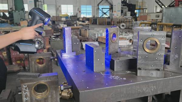
For the deepest pockets and narrow gate areas, the handheld form factor lets the operator swing the scanner into angles that a tripod-mounted system would never reach, building a complete point cloud from multiple overlapping sweeps.
Inspection Bottlenecks in Mold Verification
Conventional mold inspection often interrupts the production schedule. The tool comes off the press, gets cleaned, and travels to a CMM room where a technician runs a touch-probe routine that might take half a shift for a moderately complex mold. Only a few dozen pre-defined points are captured, and the rest of the geometry is assumed to be correct.
That approach misses wear patterns, sink marks, and subtle deformation that happen across the entire surface. When a mold is producing flash or short shots, the root cause is not always at the obvious points; it can be a gradual wall thickness variation across a curved parting line that a discrete probing plan never measured.
Thermal equilibrium is another bottleneck. Molds are designed to run at processing temperature, and dimensional checks at room temperature require correction factors that are often based on textbook values rather than the actual thermal behavior of the specific tool.
A handheld scanner can be brought to the tool while it is still warm, as long as the environment is stable enough and the scanner’s temperature compensation is active. The AlphaScan’s internal structure is designed to maintain calibration stability across a range of shop-floor temperatures, supported by INSVISION’s ISO 17025-compliant calibration process through its partner network.
This means the scan data reflects the mold as it truly exists in the molding cell, not as it cools on a granite table.
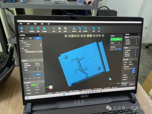
The other bottleneck is the sheer volume of data. A mold scan generates millions of points, and turning that into actionable information requires a CAD comparison that runs fast and flags the right issues. The inspection workflow needs to align the scan to the mold design, build a color map of deviations, and extract dimensional reports for specific features like gate diameters, parting line flatness, and slide fit clearances.
If the software does not handle large datasets efficiently, the inspection becomes a waiting game.
Adapting Scanning Strategy to Complex Mold Features
A structured approach to mold scanning starts with the object’s feature tree. The operator identifies the datums: tooling balls, ground surfaces, or prismatic features that tie the scan to the CAD coordinate system. For a mold with a contoured parting line, the scanner collects a dense set of points along the shut-off surfaces, then fills in the cavity and core in separate passes.
The AlphaScan’s ability to capture fine details—edge radii, small text engraving, venting grooves—makes it practical to scan the entire mold rather than just the nominal cavity shape.
This is where the AI-driven algorithm helps in stitching: when the scanner moves from a textured side wall to a smooth slide face, the system does not lose tracking because the exposure logic recognizes the transition and adjusts before the point cloud produces a misalignment error.
Deep hole inspection is a particular focus area. Ejector pin bores and guide pillar bushings often need to be verified for diameter and perpendicularity. The AlphaScan’s compact optical head can be angled into these holes to capture the first few millimeters of the bore, which is often enough to derive the axis and check the fit condition.
For deeper blind holes, the operator can use a combination of scan data and a reference pin to validate the clearance. The scanner’s software then aligns the entire data set to the CAD model and runs a GD&T analysis on the captured features, including true position of hole patterns, profile of the parting surface, and flatness of the mold base.
Thin-wall and rib structures are measured by scanning from both sides when possible, and by using the scanner’s high point density to capture the minor deflections that occur when the mold is clamped. The resulting deviation map highlights areas where the steel is deforming elastically under clamping force, a condition that a touch probe would never record because it measures only when the mold is free.
This level of insight helps toolmakers adjust packing pressure or modify the mold support pillars without waiting for the next trial run to fail.
Closing the Data Loop from Scan to Mold Correction
A scan that does not lead to a corrective action is just a picture. The value of 3D scanning for industrial molds lies in how quickly the data becomes a machined correction.
Hangzhou Insvision Technology Co.,Ltd.
Address: Building 1, No. 1399 Liangmu Road, Yuhang District, Hangzhou, Zhejiang 311121, China