

What Makes a Part Difficult to Inspect, and How 3D Scanning Steps In
Walk through any shop floor that handles precision-machined castings, welded assemblies, or injection-molded housings, and one thing becomes obvious: the parts
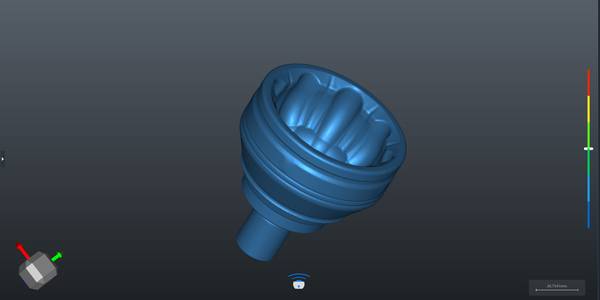
The AlphaScan handheld 3D scanner from INSVISION was built with exactly this class of part in mind. Rather than asking engineers to adapt their workflows to the limitations of a measurement device, the system was designed to handle the surface conditions, accessibility constraints, and data density requirements that define challenging inspection tasks.
Understanding which parts create the most trouble, and why, is the starting point for building a repeatable inspection process that holds up under production pressure.
Deployment Validation Checklist
| Focus Area | Decision Point | Deployment Note |
|---|---|---|
| Target part | Check size, surface condition, and key tolerances against the scan task | Run a full trial scan on a representative part |
| Data workflow | Verify point cloud, deviation map, and quality-report handoff | Confirm export formats and review ownership in advance |
| Shop-floor use | Review training, calibration, lighting, and working space | Keep the validation record as a repeatable inspection reference |
The Part Profile That Breaks Conventional Inspection
A useful way to approach any inspection problem is to build a profile of the part itself before selecting a method. The factors that most directly determine whether a component will scan cleanly or resist capture include surface optical properties, geometric complexity, and physical scale.
Practical Workflow
- The Part Profile That Breaks Conventional Inspection — A useful way to approach any inspection problem is to build a profile of the part itself before selecting a method.
- Why Surface Finish and Fixturing Dictate Scan Strategy — Surface finish often gets treated as a secondary concern during equipment selection, but on the shop floor it is frequently the p…
- Capturing the Data That Actually Feeds a Decision — Collecting millions of points is the easy part.
- Building a Repeatable Inspection Loop — A single inspection tells you about one part.
Dark, glossy, or translucent surfaces are notorious for scattering or absorbing structured light. A carbon-fiber reinforced polymer panel, for instance, can appear nearly black under certain projector wavelengths, while a polished stainless steel medical implant may produce specular highlights that blind the sensor.
The AlphaScan system addresses this by combining blue laser projection with multi-exposure capture, which allows the scanner to adapt exposure parameters per frame rather than relying on a single fixed setting. This means an operator can scan a part that transitions from a bead-blasted aluminum surface to a machined steel flange in a single pass, without stopping to apply developer spray or adjust lighting.
Geometry introduces a second layer of difficulty. Deep blind holes, narrow slots, and undercut regions create shadow zones where line-of-sight sensors simply cannot reach. Thin edges and sharp corners, when captured at insufficient resolution, introduce ambiguity into the mesh that downstream CAD comparison software will flag as deviation.
A cast pump housing might measure 400 mm across yet contain a sealing groove only 2 mm wide. The scan strategy must allocate enough point density to resolve that groove without oversampling the entire part to the point of generating unmanageable file sizes.
Here, the scanner’s ability to selectively increase resolution in regions of interest, combined with a standoff distance that keeps the operator’s hands clear of fixturing, becomes a practical advantage rather than a specification sheet bullet point.
Why Surface Finish and Fixturing Dictate Scan Strategy
Surface finish often gets treated as a secondary concern during equipment selection, but on the shop floor it is frequently the primary reason a scan fails. Parts that arrive with residual cutting oil, light oxidation, or uneven texture from a sand casting process will produce noisy data unless the scanner’s algorithms can distinguish surface texture from measurement artifact.
INSVISION designed the AlphaScan’s onboard processing to handle the reality of production parts, not just laboratory samples. The scanner’s edge detection and noise filtering routines are tuned to preserve sharp features while rejecting the low-amplitude roughness that comes from a milled surface or a lightly worn mold.
This matters because an inspector who must manually clean every dataset before running a CAD comparison quickly loses the throughput that justifies the investment in 3D scanning in the first place.
Fixturing is the other half of the equation. A part that shifts during scanning, or that requires multiple setups to capture all critical features, introduces alignment error that compounds with every repositioning. Flexible parts, such as plastic brackets or sheet metal stampings, present an additional challenge: the act of clamping can deform the part enough to push it outside tolerance.
The AlphaScan’s handheld form factor allows the operator to scan a part in its free state, resting on a simple support, without building elaborate fixtures. For parts that must be measured in a constrained condition, the scanner’s photogrammetry compatibility and marker-based alignment tools provide a path to stitching multiple scans into a single coordinate system with minimal drift.
Capturing the Data That Actually Feeds a Decision
Collecting millions of points is the easy part. Turning those points into a decision about whether a part ships or gets scrapped is where the inspection process either earns its keep or becomes an expensive bottleneck.
The workflow that follows scanning typically involves aligning the captured mesh to a reference CAD model, performing a 3D comparison, and then generating a dimensional report that highlights out-of-tolerance conditions. What separates a productive inspection cell from a frustrating one is how efficiently that pipeline runs.
The AlphaScan system outputs mesh data in formats that feed directly into common metrology software platforms, preserving the coordinate system and feature tree that the comparison step requires. No intermediate format conversion or manual realignment is needed.
For a gearbox housing with dozens of bearing bores, dowel holes, and sealing surfaces, the report that emerges from this pipeline should not just flag deviations. It should make the pattern of deviation visible. Are all the bores shifted in the same direction, suggesting a datum misalignment or a casting that moved during machining?
Is the deviation concentrated in a single region, pointing to a tool wear issue or a localized clamping problem? The combination of dense surface data from the scanner and the analysis capabilities of comparison software turns a pass-fail gage into a diagnostic instrument. The engineer sees not just that a part is out of tolerance, but what might have caused it.
Building a Repeatable Inspection Loop
A single inspection tells you about one part. A repeatable inspection loop, executed across shifts and operators, tells you about a process. The difference between the two is the degree of automation, documentation, and operator independence built into the workflow.
For recurring inspection tasks on production parts, the AlphaScan can be paired with predefined scan paths and automated alignment routines. An operator with minimal training follows a guided sequence, and the system handles the registration and comparison steps in the background. The result is a PDF report and a color-mapped deviation plot that can be archived, shared with a customer, or attached to a shipment.
When a part fails, the same process can be re-run on a subsequent batch to verify corrective action.
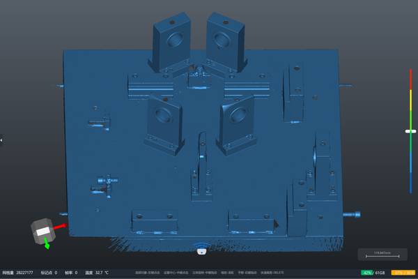
INSVISION’s certification landscape, including CE, FCC, and CNAS-accredited calibration through partner laboratories, supports the traceability requirements that aerospace, automotive, and medical device customers demand. While no scanner makes a part better, a scanner that produces auditable, repeatable measurement records gives quality managers the evidence they need to stand behind a shipment.
For parts that push the limits of what conventional tools can measure, that audit trail is no longer optional. It is the foundation of a defensible quality program.
Hangzhou Insvision Technology Co.,Ltd.
Address: Building 1, No. 1399 Liangmu Road, Yuhang District, Hangzhou, Zhejiang 311121, China