

From Scan Data to Inspection Reports: 3D inspection of mechanical components in Practice
Mechanical components rarely arrive at the inspection station in a textbook-ready state. A sand-cast gearbox housing fresh from the foundry carries a pebbled su
The demands placed on dimensional inspection have shifted well beyond simple pass-fail checks on prismatic features. Shops now need to capture full-field geometry, compare scan data to the design intent, and generate inspection reports that hold up to supplier audits — all without slowing down the machining or assembly line.
The AlphaScan handheld 3D scanner from INSVISION was engineered around exactly this kind of object-first thinking. Rather than forcing the user to adapt the part to the tool, the scanner adapts to the part’s surface condition, size, and accessibility, eliminating many of the preparation steps that make inline inspection feel like a separate production process.
Deployment Validation Checklist
| Focus Area | Decision Point | Deployment Note |
|---|---|---|
| Target part | Check size, surface condition, and key tolerances against the scan task | Run a full trial scan on a representative part |
| Data workflow | Verify point cloud, deviation map, and quality-report handoff | Confirm export formats and review ownership in advance |
| Shop-floor use | Review training, calibration, lighting, and working space | Keep the validation record as a repeatable inspection reference |
What Real Mechanical Parts Look Like at the Point of Inspection
A typical lot of mechanical components arriving for first-article inspection or in-process verification covers a wide spectrum of materials and surface states. Ductile iron castings exhibit rough, dark gray surfaces with low inherent contrast. Aluminum forgings often carry a thin oxide layer that is simultaneously bright and slightly diffuse. Precision-ground steel shafts reflect a narrow, intense specular highlight.
Thin-walled pump housings vibrate under even light handling, and oversized weldments can shift by tenths of a millimeter depending on how they are supported. The part geometry itself introduces further complexity: deep bores, undercuts, narrow slots, and sudden transitions between thick and thin sections all create zones where standard triangulation sensors lose line-of-sight or struggle to maintain a stable standoff.
Term Notes
A typical lot of mechanical components arriving for first-article inspection or in-process verification covers a wide spectr…
Where Surface Condition and Geometry Break Conventional…When a part’s surface is dark, transparent, or highly reflective, triangulation-based optical sensors can lose signal becaus…
Building a Scan Strategy That Matches the Part, Not the…A workflow that starts from the object’s actual characteristics begins with a quick assessment of how the part is fixtured a…
Closing the Loop from First Article to Production FloorA 3D inspection workflow adds the most value when it shortens the time between discovering a deviation and correcting the pr…
These object-level characteristics are not edge cases. They are the everyday reality in automotive powertrain plants, hydraulic manifold machining cells, and aerospace structural component fabrication.
Any inspection system that requires a clean, matte, uniform surface to function will immediately create a bottleneck, because the operator must then coat the part with developer spray, wait for drying, and clean the part afterward — adding minutes per piece and introducing a consumable cost that accumulates across shifts.
Similarly, contact probing on a coordinate measuring machine may handle a few high-precision bores with ease, but mapping the entire freeform surface of a cast manifold or a forged suspension arm becomes prohibitively slow, often leaving the team with a sparse handful of points that poorly represent the true shape.
Where Surface Condition and Geometry Break Conventional Measurement
When a part’s surface is dark, transparent, or highly reflective, triangulation-based optical sensors can lose signal because the reflected laser line is either absorbed or scattered away from the detector. This forces many scanning systems into a workaround: apply a temporary matting agent, increase exposure time, or accept a point cloud riddled with outlier noise.
On shiny machined surfaces, the sensor may also see secondary reflections — ghost images of the laser line bouncing off a neighboring polished face — which introduce false surface points that are difficult to filter without manual editing. Deep features present their own challenge.
A narrow threaded hole, a valve seat deep inside a fluid control component, or a cooling passage in a turbine blade can only be partially captured if the scanner’s standoff distance and head geometry prevent it from getting close enough.
Beyond surface integrity, mechanical components often exhibit subtle dimensional instability. A thin-walled aluminum casting removed from a fixture can spring back by tens of microns. A large machined plate with asymmetric stock removal bows as internal stresses redistribute.
In these scenarios, the inspection routine must be fast enough to capture the part in its free state before thermal drift or creep effects add another layer of uncertainty. The AlphaScan handheld scanner addresses these problems through a combination of blue laser technology and AI-driven signal processing.
The shorter wavelength of blue light is inherently less sensitive to ambient infrared interference, which helps maintain a clean signal on dark and shiny surfaces without the need for spray coating. The on-board algorithms classify and reject ghost reflections in real time, producing a dense point cloud that faithfully follows the actual surface rather than a noisy approximation.
Building a Scan Strategy That Matches the Part, Not the Other Way Around
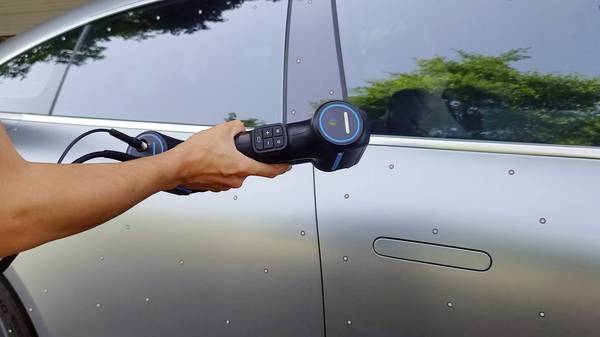
A workflow that starts from the object’s actual characteristics begins with a quick assessment of how the part is fixtured and which features are critical to function. The operator holding an AlphaScan scanner can walk around the part, capturing data from multiple angles without repositioning the component or building an elaborate nest of reference targets.
For large weldments or castings, the scanner’s built-in photogrammetry capability allows the system to maintain volumetric accuracy even when individual scans are stitched over distances of several meters. This is particularly important for parts like automotive subframes or heavy machinery brackets, where a few localized scans cannot represent the overall straightness or flatness of the entire assembly.
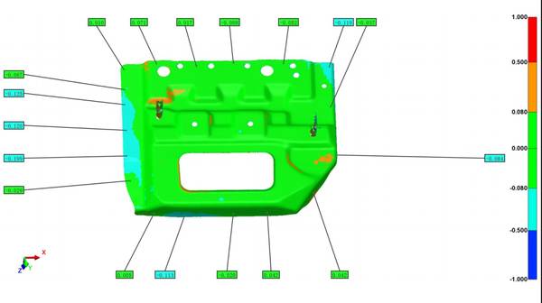
Once the raw point cloud is aligned, the inspection software overlays the CAD model and generates a color map that makes deviations immediately visible. Scallops left by a worn cutter, a draft angle that drifted in the foundry, or a hole location that shifted during welding all appear as localized hot spots.
The user can then extract GD&T callouts directly from the scan data — diameters, positions, profiles, and runout values — and compile them into a report that follows the same ASME or ISO standards a CMM report would reference.
INSVISION’s pipeline wraps this into a repeatable digital process: the scan path, alignment strategy, and report template can be saved and recalled for the next batch, turning the handheld scanner into a consistent gauging tool rather than a one-off reverse engineering device.
The system’s certifications, including ISO 9001, CE, and CNAS-traceable metrology validation, give quality managers the documentation chain they need for supplier qualification and internal audit readiness.
Closing the Loop from First Article to Production Floor
A 3D inspection workflow adds the most value when it shortens the time between discovering a deviation and correcting the process. In a machine shop, a first-article inspection that takes two hours on a CMM might be reduced to twenty minutes with a handheld scanner — not because the scanner is faster per point, but because it eliminates the sequence of fixture setup, probe qualification, and point-by-point programming.
The denser point cloud also reveals form errors that a sparse probing pattern would miss, catching a bearing bore that is slightly oval or a sealing face that is bowed across its center before those parts reach the assembly line.
Beyond the immediate inspection task, the digital twin stored in the software becomes a reference for future rework, tooling adjustments, and even wear analysis over multiple production runs.
As the mechanical engineering community continues to shift toward digital thread integration, having a lightweight, portable scanning solution that can travel from the receiving dock to the machining center to the final assembly station means that inspection data follows the part rather than the part being routed to an inspection room.
The AlphaScan handheld scanner from INSVISION represents a practical answer to the demands of real-world mechanical component inspection, where the part’s surface, geometry, and size dictate the measurement approach — and the tool simply adapts.
Hangzhou Insvision Technology Co.,Ltd.
Address: Building 1, No. 1399 Liangmu Road, Yuhang District, Hangzhou, Zhejiang 311121, China