

Handheld 3D Scanning Technology Closes the Metrology Gap in Complex Part Inspection
A machined aluminum housing for an electric vehicle power electronics module comes off the CNC mill.
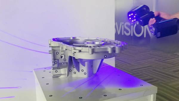
A machined aluminum housing for an electric vehicle power electronics module comes off the CNC mill. The quality team needs to verify bearing bores, seal surfaces, mounting flanges, and cooling channel interfaces—not just individual diameters, but flatness across mating faces, perpendicularity between bore axes, and surface profile on contoured sealing grooves.
A bridge CMM can measure the discrete features, but programming ties up a metrologist for hours, the part must acclimate in a temperature-controlled room, and the contoured surfaces are sampled at only a handful of points. The CMM report might pass every tolerance while a global form error goes undetected—until the assembly leaks on the line.
Deployment Validation Checklist
| Focus Area | Decision Point | Deployment Note |
|---|---|---|
| Target part | Check size, surface condition, and key tolerances against the scan task | Run a full trial scan on a representative part |
| Data workflow | Verify point cloud, deviation map, and quality-report handoff | Confirm export formats and review ownership in advance |
| Shop-floor use | Review training, calibration, lighting, and working space | Keep the validation record as a repeatable inspection reference |
This gap between the data density required and what point-based tools can economically deliver is where handheld 3D scanning technology proves its value.
The Metrology Bottleneck in Complex Part Production
The EV housing scenario repeats across mold shops, aerospace component lines, and automotive tier-one facilities. When a casting shows a subtle surface deviation or a stamped panel drifts a few tenths of a millimeter from nominal, the real cost isn’t the scrap part.
It’s the hours lost waiting for a CMM report, the bottleneck at the inspection room, and the engineering time burned trying to trace a dimensional error without full-field data.
In reverse engineering, the mismatch is equally stark. A tooling engineer tasked with recreating a worn stamping die without original CAD faces a part covered in compound curves and blend radii. Manual measurement with height gages and radius templates might capture 30 percent of the geometry needed for a usable CAD model. The rest gets approximated, and the rebuilt die drifts from the original forming behavior.
The common thread is not a lack of measurement capability, but a mismatch between the data density required and what point-based tools can economically deliver. When a single part demands thousands of measurement points to characterize its freeform surfaces, the CMM queue becomes the constraint, and the inspection report becomes a summary rather than a map.
Moving Measurement to the Part: A Shop-Floor Scanning Workflow
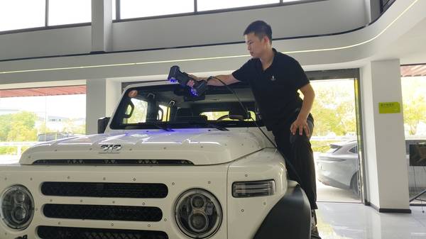
The approach that fits these conditions starts with bringing measurement to the part instead of moving parts to the measurement room. A handheld blue laser 3D scanner, specifically the INSVISION AlphaScan, brings structured-light capture directly to the production cell or tooling bench.
The scanner projects a blue laser pattern onto the surface and records the deformation of that pattern at high frame rates, building a dense point cloud that captures not just discrete features but the full surface topography.
Deployment follows a straightforward sequence:
- Preparation: The operator applies reference markers to the part or the surrounding fixture, establishing a coordinate frame that the scanner tracks in real time. For a typical mid-sized casting or stamping, marker placement takes under two minutes.
- Scanning: The scan itself proceeds as a continuous pass over the surface, with the operator watching the point cloud build on a connected laptop running INSVISION’s 3D software. Areas with deep pockets or steep draft angles get additional passes at adjusted angles. Total capture time for a part spanning 400 millimeters in its longest dimension runs in single-digit minutes.
- Data processing: The software handles multi-source alignment automatically, registering scan data to the part’s design model and generating a color-mapped deviation report that shows exactly where the as-built geometry departs from design intent. For reverse engineering jobs, the same scan data feeds directly into CAD modeling workflows, providing the dense reference geometry needed to reconstruct complex surfaces without guesswork.
Why the INSVISION AlphaScan Fits These Applications
The AlphaScan handheld scanner suits these tasks for specific technical reasons, not generic claims. Its blue laser source maintains pattern contrast on reflective and dark surfaces that scatter red laser light, reducing the need for developer spray on machined aluminum or as-cast iron.
The scanner’s large capture area—covering a field of view up to 650 mm by 550 mm—means fewer passes to cover a given part and shorter total scan cycles.
For inspection tasks, the bundled SMARPARA Q software provides GD&T evaluation tools and supports direct comparison to CAD models in common industry formats. The quality engineer works in a familiar dimensional language rather than learning a new analysis paradigm.
Hardware-software integration also matters for workflow continuity: scan data moves from capture to analysis within a single software environment, eliminating the export-import steps that introduce version confusion and alignment drift. A technician can complete a full scan-to-report cycle at the bench without walking data across the facility on a USB drive.
From Sparse Points to Full-Field Insight: Observable Outcomes
Shops adopting this approach typically see a sharp reduction in the time between part production and dimensional feedback. Where a CMM queue might delay inspection results by a shift or more, handheld 3D scanning technology delivers a full-field deviation map while the machine is still running the next part.
The qualitative shift engineers notice is the move from hunting for dimensional errors with sparse point data to seeing the entire surface at once. A flatness issue that spans a sealing face becomes immediately visible as a color gradient rather than hiding between sampled points.
The same workflow extends naturally to adjacent applications. Tooling shops use the scanner to capture as-built die geometry for springback compensation. Maintenance teams scan worn components to quantify material loss before ordering replacements. Quality departments integrate scan data into statistical process control, tracking surface trends across production batches instead of relying on a handful of discrete measurements.
In each case, the core value comes from the same capability: capturing enough data, fast enough, to make dimensional decisions on the shop floor instead of in the inspection lab.
Extending the Approach to Similar Manufacturing Environments
The pattern holds for any manufacturing environment where part geometry matters and inspection throughput limits production velocity. Handheld 3D scanning technology does not replace CMMs or traditional gaging for every task, but it fills the gap where full-field surface data is needed and point-based tools are too slow or too sparse. Typical candidates include:
- First-article inspection of castings, injection-molded parts, and sheet metal stampings with complex freeform surfaces.
- In-process verification of machining setups where waiting for a CMM report would idle a high-value machine tool.
- Reverse engineering of legacy components, worn tooling, or aftermarket parts lacking CAD documentation.
- Dimensional trending for SPC on surfaces that cannot be adequately characterized by a few discrete touch points.
The decision to adopt starts with identifying the parts where the metrology gap costs real time and real scrap, then evaluating whether a handheld system can close it.
Closing the Gap
For quality managers and manufacturing engineers, the bottleneck is rarely the measurement technology itself—it’s the mismatch between the data density a complex part demands and the throughput a point-based system can deliver. Handheld 3D scanning technology, deployed with a system like the INSVISION AlphaScan, shifts dimensional inspection from a scheduled lab activity to an on-demand shop-floor resource.
The result is faster feedback, more complete surface data, and the ability to catch form errors that point sampling would miss. In an industry pushing for tighter tolerances and shorter lead times, that capability moves from nice-to-have to operational necessity.
Hangzhou Insvision Technology Co.,Ltd.
Address: Building 1, No. 1399 Liangmu Road, Yuhang District, Hangzhou, Zhejiang 311121, China