

How to Match White Light 3D Scanners to Tight-Tolerance Part Inspection Needs?
white light 3d scanner: Why Tight-Tolerance Part First Article Inspection Is a High-Stakes Bottleneck Why Tight-Tolerance Part First Article Inspection Is a.
Why Tight-Tolerance Part First Article Inspection Is a High-Stakes Bottleneck
Western manufacturing has shifted. Aerospace suppliers now face AS9102 first article inspection requirements that demand ballooned documentation for every characteristic, medical device makers carry ISO 13485 traceability obligations from raw stock to finished implant housing, and automotive EV programs under IATF 16949 compress launch timelines while stator assemblies grow more complex.
The common thread is this: tight-tolerance parts can no longer be verified with spot checks and a CMM report stapled to a traveler.
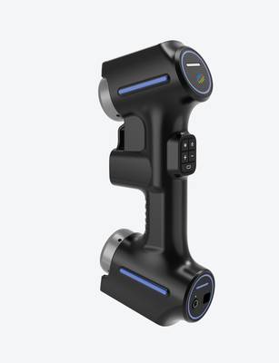
Deployment Validation Checklist
| Focus Area | Decision Point | Deployment Note |
|---|---|---|
| Target part | Check size, surface condition, and key tolerances against the scan task | Run a full trial scan on a representative part |
| Data workflow | Verify point cloud, deviation map, and quality-report handoff | Confirm export formats and review ownership in advance |
| Shop-floor use | Review training, calibration, lighting, and working space | Keep the validation record as a repeatable inspection reference |
Scenario Snapshot
A practical way to read the article is through this scenario:
- Why Tight-Tolerance Part First Article Inspection I…: Western manufacturing has shifted.
- 6 Critical Constraints to Map Before Evaluating Whi…: The key takeaway is simple: a white light 3D scanner can only improve an inspection workflow if the constraints ar…
- Common Capture and Alignment Risks That Derail Whit…: The shift toward automated dimensional inspection has put white light 3D scanner systems into more production cell…
First article inspection is where the bottleneck forms. A turbine blade with fifty-plus GD&T callouts, an implant housing with compound-curvature sealing surfaces, an EV stator assembly with lamination stack runout tolerances measured in microns.
Teams often buy a white light 3D scanner expecting it to solve the throughput problem, then discover the real constraint: the scanner was never matched to the part geometry, surface finish, fixture access, or the specific data deliverable the quality system requires. The result is inconsistent scan data, repeated rescans, gaps in AS9102 ballooned characteristics, and quality traceability that falls apart under audit.
The pain is not the scanner itself. It is the misalignment between what the tool captures and what the inspection task actually demands. A field solution engineer sees this pattern repeatedly: the scan object defines the capture strategy, the inspection requirement defines the alignment approach, and the site constraint defines whether a measurement is even repeatable.
Skip any one of those, and the FAI package becomes a fire drill instead of a controlled process. The rest of this article lays out a working framework for matching scanner capability to real inspection requirements, without the marketing gloss.
6 Critical Constraints to Map Before Evaluating White Light 3D Scanners
The key takeaway is simple: a white light 3D scanner can only improve an inspection workflow if the constraints are mapped before the purchase. Skipping this step is the most common reason factories end up with underused equipment and unchanged cost structures.
Start with part geometry. A free-form turbine blade and a prismatic valve body create different capture challenges. If internal cavities or undercuts are present, the scan strategy changes immediately. Material properties come next. Reflective stainless steel, matte carbon fiber, and translucent medical polymers each respond differently to structured light. A scanner that handles one may struggle with another.
Tolerance requirements drive the entire validation approach. ASME Y14.5 callouts, critical feature bands, and calibration traceability determine whether the system can support first-article inspection or just rough verification. Site conditions matter equally. Factory floor vibration, ambient light shifts, and temperature swings in a production bay can degrade data quality faster than any software setting.
Takt time and data deliverables complete the picture. In-line inspection demands cycle times that lab-based scanning does not. Full-field deviation maps, audit-ready reports, and integration with QMS, CAD, or SPC software define whether the output is actually usable downstream. INSVISION application evaluations address these six constraints before recommending any white light 3D scanner configuration.
Common Capture and Alignment Risks That Derail White Light 3D Scanner Performance
The shift toward automated dimensional inspection has put white light 3D scanner systems into more production cells than ever before. That is good for throughput, but it also exposes a problem many shops do not anticipate until first-article inspection stalls. The scanner itself is rarely the bottleneck. The mismatch between scan strategy and the physical constraints of the part is what creates the real cost.
Capture failures show up first. Reflective machined surfaces, polished welds, or coated castings can produce glare that wipes out entire patches of point data. Deep recesses and internal bores create shadowing that leaves voids in the mesh. Small critical features, such as a 0.5 mm radius fillet or a tight GD&T callout on a sealing groove, often lack enough point density to make a tolerance check defensible.
The scan looks complete on screen, but the data behind it is too thin for reliable measurement.
Alignment inaccuracies compound the problem. If reference markers are placed without considering part geometry, the scanner can lock onto a local feature and propagate alignment error across the full surface. Fixturing drift between scan passes introduces the same issue. Worse, when the scan data cannot be tied back to the CMM datum framework used for the customer drawing, traceability breaks.
A supplier can spend hours aligning scan results to nominal CAD only to find the coordinate system does not match the customer’s inspection report.
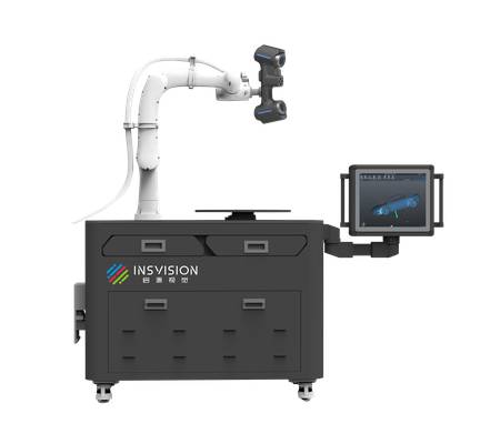
Then come the unplanned rescan cycles. Operators go back to fill data gaps, adjust marker positions, or rotate the part for better line of sight. Each cycle adds time, but it also adds variability. A less experienced operator may rescan only the missing area and merge it poorly, creating a blended dataset that passes visual review but fails a detailed audit.
The same part scanned by two different operators can yield two different results.
From a cost perspective, these failures cascade quickly. First-article submission dates slip. Inspection labor hours climb because someone has to validate every rescan and rework the report. Rework on the manufacturing side often follows, since a questionable scan cannot be used to approve a process. Customer audits may flag inconsistent inspection records, forcing a deeper review of the entire quality workflow.
The scanner was supposed to reduce lead time, but without a capture plan matched to the part, it adds hidden operational burden.
INSVISION addresses these risks by treating scan strategy as part of the inspection process, not an afterthought. The focus is on defining the capture envelope, marker layout, and datum alignment before scanning begins, so the white light 3D scanner produces a complete, traceable dataset on the first pass.
That is where the operational value actually sits: fewer rescans, less operator-dependent variation, and inspection data that holds up under audit.
How to Align White Light 3D Scanner Capabilities to Your Workflow Requirements
White light 3D scanning has moved from a laboratory curiosity into a practical shop-floor metrology tool, but the buying process still trips up a lot of teams. The problem is rarely the scanner itself. It is the mismatch between what a datasheet promises and what a specific inspection workflow actually demands.
A scanner that performs brilliantly on a granite surface plate in a climate-controlled lab can struggle next to a machining center, and a unit optimized for shiny medical implants may be overkill for large castings with generous tolerances.
Aligning scanner capabilities to workflow requirements means ignoring the urge to compare headline specifications in isolation. Instead, each constraint identified earlier in the evaluation process should map directly to a capability category that can be tested and verified. This section walks through that mapping logic.
Start with part surface conditions. If your Section 2 constraint list includes high-reflectivity components, such as polished turbine blades or machined aluminum housings, do not simply look for a scanner with a high megapixel count. Ask about light intensity adjustability and whether the system supports multi-exposure capture modes. White light scanners illuminate the part and read the reflected pattern.
A highly reflective surface can saturate the sensor at one exposure setting while leaving darker adjacent areas underexposed. Multi-exposure capture takes several images at different exposure levels and fuses them, which is often the difference between capturing a complete dataset on the first pass and triggering repeated rescans.
For parts with mixed finishes, such as a casting with machined datum pads, this capability matters more than raw resolution.
For shop-floor deployment, the constraint list should include vibration, temperature variation, and airborne contaminants. Here the evaluation shifts from optical performance to mechanical and environmental resilience. Confirm whether the scanner housing is sealed against dust and coolant mist, whether the internal optics are isolated from vibration, and how the unit handles thermal drift.
Some scanners need frequent recalibration when ambient temperature shifts by a few degrees. Others maintain stability across a wider operating range. If the scanner will sit near a stamping press or a robotic weld cell, vibration resistance and recalibration intervals become primary evaluation criteria, not secondary notes.
High-throughput environments introduce a different set of priorities. If the workflow requires measuring dozens or hundreds of parts per shift, scan speed and automated alignment features take precedence. Scan speed determines how quickly the sensor acquires the point cloud. Automated alignment determines how much operator intervention is needed between scans.
A scanner that requires manual pre-alignment or repeated best-fit adjustments on each part will consume labor hours that erode the throughput advantage. Look for features that reduce operator touch time, such as automated part recognition, pre-defined measurement templates, and one-click alignment routines.
The key point is that no universal performance ranking answers these questions. A scanner with the highest nominal accuracy may be the wrong choice for a rough shop-floor application where environmental factors dominate error sources. A scanner with moderate accuracy may be ideal for a high-mix inspection cell where flexibility and speed matter more than sub-micron precision.
The optimal solution depends entirely on the constraint map built in Section 2.
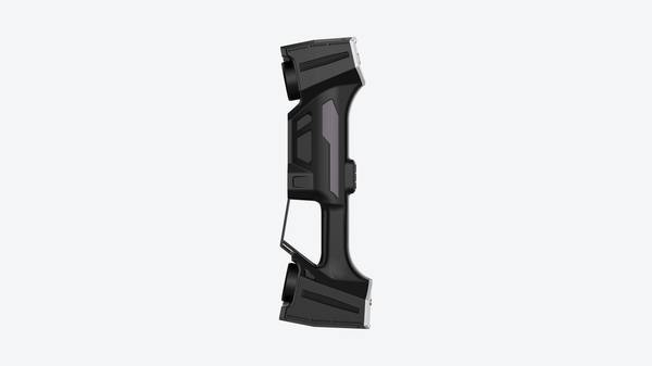
INSVISION approaches this alignment problem through application engineering support rather than leaving the customer to interpret spec sheets alone. The company provides industrial white light 3D scanning solutions and works with clients to configure the system around specific part types, tolerance requirements, and operating conditions.
That means the evaluation conversation starts with the parts you measure, the environment you work in, and the deliverables your downstream process needs, then works backward to scanner settings, fixturing, and validation methods.
When evaluating any white light 3D scanner for a constrained workflow, treat the fit assessment as a verification exercise. Define the part family, the GD&T callouts that matter, the environmental conditions at the measurement location, and the required inspection cadence. Then test the scanner against those conditions. Run a gage repeatability and reproducibility study on representative parts.
Measure a known artifact at the start and end of a shift to check thermal stability. Scan a high-reflectivity part without spray coating and evaluate data completeness. These tests reveal real-world performance far more reliably than any specification table.
The result is a fit assessment based on measured behavior in your environment, not on marketing claims. That is the only way to ensure the scanner you select will perform the work you actually need it to do.
Validation Checklist and Practical Deployment Boundaries
Industrial buyers rarely fail because they picked the wrong scanner category. They fail because they validated on the wrong parts, with the wrong operators, and then discovered the data pipeline did not fit their quality system. A white light 3D scanner can look excellent on a calibration artifact and still struggle on a production casting with mixed reflectivity, edge breaks, or deep pockets.
The checklist below is written for teams that want to run validation themselves, or alongside INSVISION, without relying on demo-room results.
First, test with a representative production part sample. Not a gauge block. Not a ceramic sphere. Select three to five parts that carry the surface conditions your line actually produces: machined faces, as-cast areas, weld seams, plastic textures, or coated surfaces. Capture the same GD&T callouts you would report in a first-article inspection.
A scanner that passes on a matte calibration panel may still produce noisy data on a bright machined flange or a translucent polymer housing. Run the full scan-to-report workflow on these parts before making any procurement decision.
Second, verify repeatability across multiple operators and scan sessions. Have at least two or three people run the same part on different shifts. Operators change scan distance, part orientation, and exposure settings. If your results shift by more than your acceptable tolerance band when a second operator takes over, you have a training or workflow problem that no scanner specification will solve.
Record the full measurement routine, including fixture setup and software steps, so the validation reflects how the tool will actually be used day to day.
Third, confirm data output compatibility with your existing QMS, CAD, and SPC software. Many teams overlook this until deployment week. The scanner may generate a dense point cloud, but your quality team needs a dimensional report that drops into Minitab, Q-DAS, or an in-house SPC package. If you need a color map, confirm it exports to a format your document control system accepts.
If you need CAD comparison, confirm the alignment workflow matches how your design team defines datums. Manual data entry between systems becomes a bottleneck quickly, and it erodes the efficiency gain you bought the scanner for in the first place.
Fourth, assess deployment time and labor requirements for both initial setup and routine daily use. Time the full cycle: part staging, scanner warm-up, calibration check, scan, alignment, extraction, report generation. Do not assume the scan itself is the bottleneck. Often the hidden cost sits in alignment, cleaning mesh data, or manually extracting features.
Ask your provider to run this timing exercise on your parts, with your operators present, and record the numbers.
Now for realistic boundaries. White light 3D scanning excels at full-field surface inspection of external and accessible internal features. It is the right tool when surface form, profile, and feature position are the primary conformance criteria. It is less suited for deep hidden cavities, highly reflective or transparent surfaces without preparation, or line-of-sight inaccessible geometry.
If your inspection task is primarily internal thread verification or bore geometry deep inside a part, a different measurement approach may be required. The scanner is not a universal replacement for every metrology tool on the floor; it is a high-density surface data tool that should be matched to the right inspection tasks.
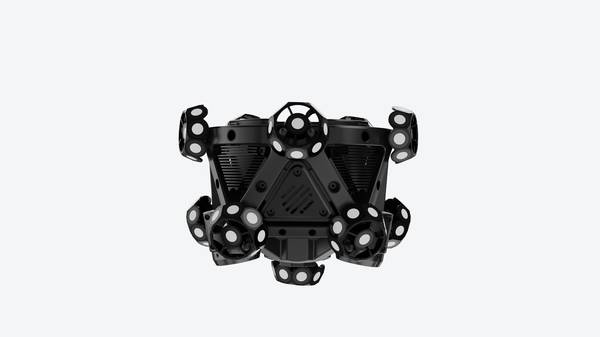
INSVISION application engineers can support this validation by designing custom test plans tied to your specific quality requirements. That means selecting the right part features, defining the pass-fail criteria, and running the timing and repeatability exercises on your floor rather than in a demo lab.
For Western industrial teams working under ISO 17025 calibration and traceability expectations, this kind of structured validation is not optional. It is how you keep the procurement decision defensible and the deployment predictable.
Hangzhou Insvision Technology Co., Ltd.
Address: Building 1, No. 1399 Liangmu Road, Yuhang District, Hangzhou, Zhejiang 311121, China
Copyright © Hangzhou Insvision Technology Co., Ltd. All rights reserved.
Copyright © Hangzhou Insvision Technology Co., Ltd. All rights reserved.