

How to Validate a 3D Part Scanner for Industrial Quality Inspection
3d part scanner: Why Proper 3D Part Scanner Validation Reduces Implementation Risk Quality teams evaluating a 3D part scanner often fixate on headline.
Why Proper 3D Part Scanner Validation Reduces Implementation Risk
Quality teams evaluating a 3D part scanner often fixate on headline accuracy numbers before considering whether the system will hold up against their actual part geometries and shop-floor conditions. That sequencing creates risk. A scanner that performs well on a matte, medium-sized validation block may struggle with a polished aerospace bracket or a medical device component with deep, narrow pockets and reflective surfaces.
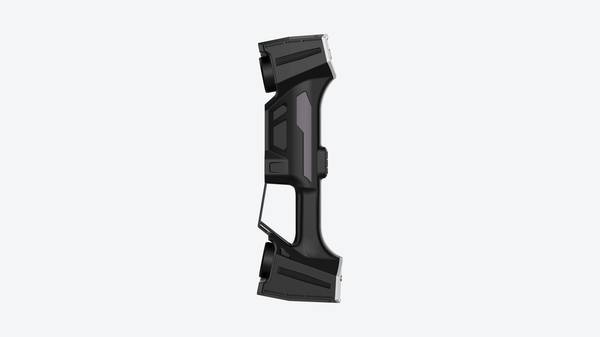
Key Points at a Glance
- Quality teams evaluating a 3D part scanner often fixate on headline accuracy numbers before considering whether the system will hold up against…
- A quality lead evaluating a 3D part scanner often discovers the misalignment only after first-article inspection stalls.
- “Will this scanner actually work on our parts, in our facility, with our tolerance stack?” That’s the question quality leads should ask before a…
- Plain text, 100–180 words per section, no markdown.
Proper validation flips the evaluation order. Start with the workpiece, not the spec sheet. Define the smallest feature that must be resolved, the tightest GD&T callout that must be verified, and the surface finishes present across the part family. Then test the 3D part scanner against those conditions, including the lighting, vibration, and temperature swings typical of the inspection area.
Deployment Validation Checklist
| Focus Area | Decision Point | Deployment Note |
|---|---|---|
| Target part | Check size, surface condition, and key tolerances against the scan task | Run a full trial scan on a representative part |
| Data workflow | Verify point cloud, deviation map, and quality-report handoff | Confirm export formats and review ownership in advance |
| Shop-floor use | Review training, calibration, lighting, and working space | Keep the validation record as a repeatable inspection reference |
This section outlines a practical validation framework for quality leads, manufacturing engineers, and technical procurement advisors evaluating INSVISION industrial 3D scanners. The goal is straightforward: confirm measurement repeatability, data completeness, and workflow fit before committing to deployment. That reduces the chance of discovering a fundamental mismatch after the system is already on the floor.
Common Risks of Misaligned 3D Part Scanner Selection
A quality lead evaluating a 3D part scanner often discovers the misalignment only after first-article inspection stalls. The decision that looks sound on a spec sheet can create real production pain when the scanner does not match the workpiece, the inspection workflow, or the data environment.
Three risk areas show up repeatedly in Western manufacturing settings. First, data consistency gaps on high-reflectivity metal parts or deep-cavity geometries, such as aerospace turbine blades and medical implant components. If the scanner cannot handle mirror-like surfaces or narrow recesses without excessive prep or repeated scan cycles, inspection timelines slip and operators lose confidence in the dataset.
Second, throughput mismatch on high-volume automotive tier 1 lines. A slow scan cycle that might be acceptable in a lab becomes a lean manufacturing bottleneck when it sits inside a production cell. Third, software interoperability problems with existing CAD, metrology, or QMS tools aligned to ASME Y14.5 or ISO 17025. Manual reformatting between scan data and downstream systems multiplies human error and erodes traceability.
These risks are avoidable. Structured pre-purchase validation should focus on the specific workpiece set, required GD&T callouts, cycle time targets, and the software stack already in use. INSVISION industrial 3D scanners are best evaluated against those conditions, not against generic scanner categories.
The point is not to buy the most advertised device, but the one that fits the inspection task and the data pipeline without forcing the team to change how it works.
Core Validation Criteria for Industrial 3D Part Scanners
“Will this scanner actually work on our parts, in our facility, with our tolerance stack?” That’s the question quality leads should ask before any demo. Not “what’s the spec sheet resolution,” but whether the system survives contact with real workpieces and real shop-floor conditions.
The answer depends on how the scanner builds geometry. Structured light systems project known fringe patterns and reconstruct surfaces from deformation. Laser triangulation sweeps a line or spot across the part and calculates depth from the reflected angle. Both produce point clouds later meshed into polygonal models. Neither approach is universally better. Shiny, dark, or translucent materials challenge optical capture.
Deep undercuts and internal bores remain blind spots for many line-of-sight devices. Scanner type sets boundary conditions long before accuracy claims matter.
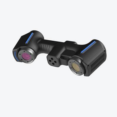
Validation therefore means testing against your exact part family. A checklist built around generic marketing specs misses the point. The four categories below—part compatibility, performance alignment, operational fit, and data interoperability—turn evaluation into a structured engineering exercise, not a vendor-controlled demo.
INSVISION industrial 3D scanners can be assessed through the same evidence-based sequence, with each criterion verified against the team’s own inspection tasks rather than published data sheets.
How INSVISION 3D Part Scanning Solutions Support Validated Deployment
Plain text, 100–180 words per section, no markdown.
The shift toward digital quality records and CAD-based inspection has changed how Western manufacturers evaluate metrology equipment. More teams now ask for proof of performance on their own parts before a purchase order is issued. That is a sensible change.
A 3D part scanner can look capable in a brochure but behave differently when it meets a cast aluminum bracket, a carbon fiber duct, or a shop floor with vibration and variable lighting. INSVISION designs its industrial 3D part scanning portfolio for exactly these conditions. The equipment is built around common production materials and typical factory environments, not just clean lab settings.
It also supports the CAD and metrology software packages most Western engineering teams already use. From a validation standpoint, that reduces integration risk.
Where INSVISION supports the validation process most directly is through controlled demo scans. A team can send its own production parts, or arrange an on-site evaluation, and measure the scanner’s performance against real requirements. Tolerance, throughput, and data format are the three variables that matter.
A demo scan shows whether the scanner holds the required GD&T callouts on a specific feature, completes a scan within the cycle time, and exports data that downstream software can consume without rework. This is not a generic demonstration. It is a direct test of the same workflow the team will run after deployment.
This approach fits the validation framework outlined earlier because it removes guesswork. Instead of relying on datasheet values, the evaluation team sees actual point cloud density, edge definition, and repeatability on the parts they care about. That is particularly useful for first-article inspection, where a scanner must prove itself against an approved CAD model and a defined tolerance band.
It also helps in aerospace MRO or medical device work, where material finish and part geometry vary widely. By testing before committing, procurement and quality teams can separate scanner capability from marketing claims. INSVISION’s demo scan offering is structured around that principle. The goal is not to sell a spec sheet. The goal is to let the measurement data speak first.
3D Part Scanner Validation FAQs for Quality Teams
Quality leads evaluating a 3D part scanner for first-article inspection or in-process checks often face the same four questions. The answers matter less than how you validate them on your own parts.
Can a 3D part scanner support ASME Y14.5 GD&T inspection requirements?
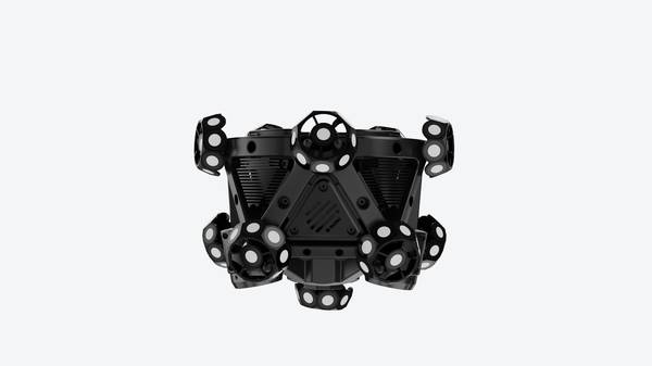
Many industrial 3D part scanners are engineered to support geometric dimensioning and tolerancing inspection, but the real test is whether the scanner holds up on your specific tolerances. Run a controlled demo on production components with known GD&T callouts, including tight position and profile tolerances. Check repeatability across multiple setups and operators before trusting advertised accuracy specs.
What surface finishes work with industrial 3D part scanners?
Compatibility varies by technology type. Most industrial-grade scanners handle common manufacturing finishes, from machined metal to molded plastic. The risk areas are high-reflectivity surfaces, textured finishes, and semi-transparent materials. Test on your exact part surfaces.
If the scanner struggles, ask whether scanning spray or matting agents are acceptable in your workflow, or whether the supplier can adjust exposure settings to compensate.
Do 3D part scanners integrate with existing quality management software?
Most industrial 3D part scanners support standard 3D file formats and offer integration with popular metrology and QMS tools. Before purchase, verify direct compatibility with your specific software stack. Ask which formats export cleanly, whether inspection reports flow into your QMS without manual rework, and what happens with legacy inspection data.
Can 3D part scanners be used on the shop floor, or only in metrology labs?
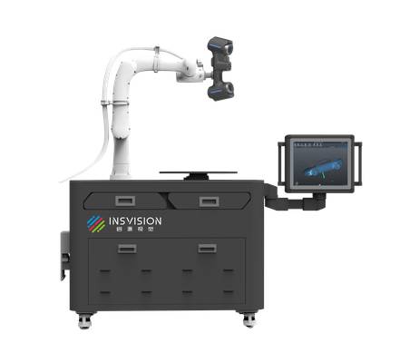
Many modern industrial 3D part scanners are built for shop-floor deployment, with features to mitigate vibration and ambient lighting interference. INSVISION industrial 3D scanners, for example, are positioned for use outside controlled lab environments. Still, test in your actual operating environment. A scanner that works in a quiet metrology lab may behave differently next to a stamping press or CNC line.
Confirm consistent results under real production conditions before committing.
Hangzhou Insvision Technology Co., Ltd.
Address: Building 1, No. 1399 Liangmu Road, Yuhang District, Hangzhou, Zhejiang 311121, China
Copyright © Hangzhou Insvision Technology Co., Ltd. All rights reserved.
Copyright © Hangzhou Insvision Technology Co., Ltd. All rights reserved.