

When Freeform Surfaces Defeat Conventional Measurement
A freeform surface is not a defect. It is a deliberate design choice that appears in turbine blades, orthopedic implants, automotive body panels, and consumer e
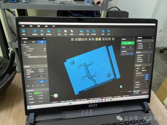
Conventional metrology struggles with freeform surfaces for a reason that goes deeper than operator skill. The coordinate measuring machine stylus must physically touch the surface at discrete points, and the number of points required to characterize a sweeping compound curve quickly exceeds what any production cycle can tolerate.
Profile tolerance zones on freeform surfaces often span the entire part, and a point cloud of 40 or 400 measured locations cannot credibly represent conformance across a continuous surface. Engineers compensate by measuring more points on fewer parts, which increases inspection time, creates bottlenecks, and still leaves large areas of the surface uninspected.
Deployment Validation Checklist
| Focus Area | Decision Point | Deployment Note |
|---|---|---|
| Target part | Check size, surface condition, and key tolerances against the scan task | Run a full trial scan on a representative part |
| Data workflow | Verify point cloud, deviation map, and quality-report handoff | Confirm export formats and review ownership in advance |
| Shop-floor use | Review training, calibration, lighting, and working space | Keep the validation record as a repeatable inspection reference |
The gap between the nominal CAD model and the physical verification data grows wider as geometries become more organic.
Object Characteristics That Challenge Every Measurement Strategy
Freeform surfaces concentrate risk in specific geometric features that do not respond well to traditional inspection logic. The core problem is that no single measurement approach works across all zones of the same part. A turbine blade root may have tight planar tolerances suitable for contact probing, while the airfoil section demands full-field surface data with sub-millimeter point spacing.
The transition zone between these regions is where many inspection plans fail.
High-gloss or polished surfaces introduce another layer of difficulty. Many freeform parts in medical and aerospace applications are mirror-finished to reduce stress concentrations or improve fluid dynamics.
Structured light scanners project fringe patterns onto the surface, and glossy finishes scatter the projected pattern unpredictably, creating noise and data dropout in the very regions where surface continuity matters most. Translucent or semi-transparent materials such as certain polymers and silicones compound the problem further because the projected light penetrates the surface rather than reflecting cleanly from it.
Deep pockets, narrow slots, and undercut regions that are common in molded freeform parts create shadow zones where line-of-sight optical techniques cannot acquire data at all. The surface geometry that defines the part also hides from the sensor.
Mapping a Scan Strategy to the Surface Reality
Scanning a freeform surface accurately requires treating the part as a collection of distinct geometric zones, each with its own access, reflection, and resolution requirements. The first step is not powering on the scanner. It is studying the CAD model to identify high-curvature areas, transition fillets, and any features that will serve as alignment references later.
For a part that has no flat datum planes, the alignment strategy often relies on best-fit registration against the nominal CAD model, which means the scan data must be dense enough and clean enough to converge reliably.
A handheld scanner like the AlphaScan changes the tactical approach because the operator can orient the device to match the local surface normal continuously. On a highly swept impeller blade, the scan path follows the curvature rather than working from fixed tripod positions. Where surface finish causes glare, the operator can apply a thin layer of temporary matting spray or adjust the scanner exposure settings on the fly.
INSVISION has built the AlphaScan with the flexibility to handle these field adjustments without recalibrating the system. For deep cavities or undercut features, the scanner can be tilted and repositioned to capture data from multiple angles, and the software stitches the overlapping scans into a unified point cloud on the fly.
The result is a single dataset that covers the entire surface without stitching artifacts in the transition zones.
The scan strategy must also account for edge definition. Freeform surfaces often terminate at knife edges or thin trailing edges, and these regions are critical to aerodynamic or fluid performance. Contact probes tend to skid off such edges. Optical scanning can capture them if the point density is high enough and the scanner resolution can resolve the edge radius cleanly.
The AlphaScan can be operated at close standoff distances to increase point density around critical edge features, giving the inspection software enough data to extract a meaningful edge profile rather than a rounded approximation.
From Point Cloud to Inspection Report in a Production Workflow
The raw scan data is a point cloud that may contain millions of coordinates. The value of the scan is not the data volume but the speed with which the data can be turned into actionable conformance information. The target workflow in a production environment is to align the scan data to the CAD model, generate a color-mapped deviation plot, and export a pass/fail report before the next part comes off the line.
Alignment is the first decision point. For freeform parts without machined datums, a best-fit alignment minimizes the overall deviation between the scan and the CAD nominal. This is not a trivial computation when the part has no dominant planar features. The software must iterate across the entire surface, and the quality of the alignment depends on the scan coverage.
Gaps in the scan data create local minima that bias the alignment. This is why the scan strategy must aim for complete coverage on the first pass.
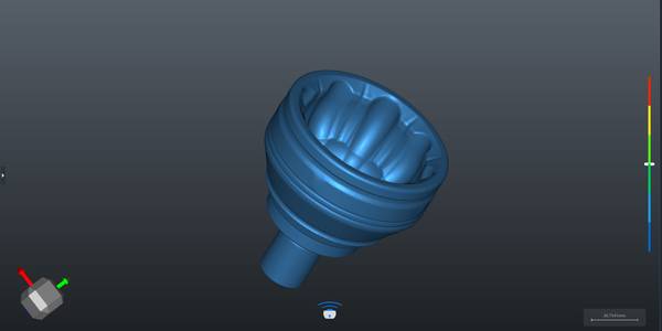
Once aligned, the comparison between scanned surface and CAD model is typically displayed as a color map overlaid on the 3D geometry. Areas in green are within tolerance. Red and blue zones indicate positive or negative deviation. The engineer can click on any region to extract a cross-sectional profile or a local dimension.
For a freeform automotive panel, this might mean checking the flush-and-gap condition along a mating edge. For a medical implant, it might mean verifying the articular surface curvature against the design envelope.
The AlphaScan data pipeline supports export to common inspection platforms, and INSVISION provides workflow integration that allows the same scan data to serve multiple downstream uses: first article inspection, in-process checks, and final quality records.
The report itself must be traceable. A good inspection report for a freeform part includes the alignment method, the tolerance zone definition, the color scale range, and the pass/fail criteria. It does not need to include every point. It needs to prove that the entire surface has been evaluated. The deviation map serves as that proof.
When Freeform Inspection Becomes a Production Capability
The highest-value outcome of 3D scanning for freeform surfaces is not an inspection report. It is the ability to move the data into tool correction, process adjustment, and faster iteration. When a first article scan reveals a systematic deviation in a specific curvature zone, the mold or die can be modified before more parts are produced. The scan data becomes the feedback loop that shortens trial-and-error cycles.
The AlphaScan is designed for this kind of connected workflow. It is a handheld scanner that operates at production speed, and its data output is compatible with the CAD and inspection software that quality teams already use. INSVISION has positioned the system as a practical tool for freeform surface measurement, not a laboratory instrument that requires a controlled environment.
The certifications behind the product, including CE, FCC, and CNAS-recognized calibration, support its use in regulated industries where measurement traceability is mandatory.
Freeform surfaces will continue to appear in more products as design tools make complex geometry easier to model and manufacturing processes such as additive manufacturing and multi-axis milling make them easier to produce. The inspection capability must keep pace.
A 3D scanning approach that is built around the actual surface characteristics of the part, rather than forcing the part to conform to the limitations of the measurement tool, turns a difficult inspection problem into a repeatable process.
Hangzhou Insvision Technology Co.,Ltd.
Address: Building 1, No. 1399 Liangmu Road, Yuhang District, Hangzhou, Zhejiang 311121, China