

When a Worn Gear Blank Has No Drawing: Reverse Engineering Mechanical Components with 3D Scanning
The maintenance team pulls a heavily worn spline shaft from a gearbox that was built before digital records existed. There is no CAD file, no paper drawing, and
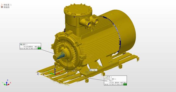
Mechanical components present a distinct set of measurement challenges that differ from organic shapes or simple prismatic parts. A typical machine element — whether it is a pump housing, a connecting rod, a turbine blade, or a gear carrier — often combines freeform surfaces, tight tolerance bores, thin walls, and areas with high reflectivity from machining or polishing.
The part may be too large to place on a CMM table, or it may have internal passages that a touch probe cannot reach. When the goal is to reverse engineer the part, the scanner must capture the as-is geometry, including any wear, distortion, or previous repair layers, because the replacement part often needs to match the worn condition to fit the surrounding assembly.
Deployment Validation Checklist
| Focus Area | Decision Point | Deployment Note |
|---|---|---|
| Target part | Check size, surface condition, and key tolerances against the scan task | Run a full trial scan on a representative part |
| Data workflow | Verify point cloud, deviation map, and quality-report handoff | Confirm export formats and review ownership in advance |
| Shop-floor use | Review training, calibration, lighting, and working space | Keep the validation record as a repeatable inspection reference |
This is a different task from inspecting a new part to a nominal CAD model; it requires a handheld scanner that can adapt to the part, not the other way around.
## Object Snapshot: The Real Condition of Mechanical Parts in the Field
A used mechanical component rarely matches the ideal geometry of a textbook drawing. The spline shaft mentioned earlier might have fretting corrosion on the spline flanks, a bearing journal that is 0.03 mm undersized from years of rotation, and a keyway that has been peened by a loose key.
The material is likely alloy steel, possibly with a ground finish on the bearing diameter that is mirror-like and difficult for many optical scanners. The threaded section is a helical groove with sharp crests that can create shadowing. The oil seal diameter is a ground surface where a scanner must capture the subtle wear groove that caused the leak.
All these features exist on a single part that is maybe 300 mm long and 60 mm in diameter. The part is not huge, but the density of critical features is high.
Key Points at a Glance
- A used mechanical component rarely matches the ideal geometry of a textbook drawing.
- For a part like the spline shaft, a handheld 3D scanner such as the INSVISION AlphaScan makes it practical to capture fine details without needi…
- The raw scan data alone is not a finished reverse engineering output.
- When selecting a 3D scanning approach for reverse engineering mechanical components, the part’s surface finish and feature size are the primary…
A different class of component is a cast pump volute. The part is larger, with a dark, somewhat rough surface from sand casting, and it contains complex internal flow passages that are inaccessible to calipers or a fixed CMM. The reverse engineering goal here is to create a CAD model that can be used to cast a new housing that fits the existing impeller and mounting flange pattern.
The surface is not highly reflective, but the texture is uneven, and the part may have draft angles and parting line flash that need to be segmented out of the final model. The weight of the part may require it to be scanned on the floor or on a low stand, with the operator moving around it.
## The Scanning Strategy: Adapting to Part Geometry, Not Forcing It
For a part like the spline shaft, a handheld 3D scanner such as the INSVISION AlphaScan makes it practical to capture fine details without needing to fixture the part in a rigid, indexed setup. The operator can hold the part by the undamaged end, or lay it on a bench with a few simple supports, and scan from multiple orientations.
The AlphaScan’s ability to track the part’s position dynamically means the spline, the bearing seat, the thread, and the keyway can all be captured in a single continuous scan session, without targets on the part if the geometry has enough natural features. The scanner’s laser lines can be adjusted to handle the bright ground journal;
instead of trying to overpower the reflectance with spray coatings, the operator can tilt the scanner slightly to reduce the direct return and still get a clean point cloud on the shiny surface. The thread is captured by scanning along the shaft axis, letting the laser profile the crest and root of the thread form.
For the pump volute, the scanning approach is different. The part is stationary, and the operator walks around it with the AlphaScan. The scanner’s volume and the part’s external shape can be captured in marker mode or with geometry-based alignment. The internal passages are the real challenge.
A handheld scanner can be pointed into the suction and discharge ports to capture the visible interior surfaces, even if full internal coverage requires a borescope-style probe. The resulting point cloud is a mix of the external casing, the flange faces, and as much of the internal volute as can be seen. The goal is not always 100% internal coverage;
it is to capture enough to define the volute cross-section and the cutwater geometry, which are the critical flow features.
In both cases, the scan data is a dense point cloud, often with millions of points. The next step is to process the data into a usable CAD model. For the shaft, the workflow involves extracting cross-sections through the spline to reverse engineer the tooth profile, checking the bearing journal diameter against a nominal value derived from the mating bearing, and modeling the thread as a helical sweep.
The point cloud is segmented into logical regions — cylindrical surfaces, planar faces, spline flanks — and a parametric CAD model is built from these extracted features. For the pump housing, the approach is more freeform: the point cloud is used to generate a NURBS surface model that captures the organic shape of the volute, and the flange bolt pattern is extracted as a 2D sketch.
## From Point Cloud to Trusted Drawing: Data Handling and Verification
The raw scan data alone is not a finished reverse engineering output. A mechanical component must be defined with tolerances, surface finish requirements, and material callouts. The reverse engineering process must include a verification step where the final CAD model is compared back to the original scan data.
The INSVISION AlphaScan ecosystem includes software that can overlay the CAD model onto the point cloud and generate a color map of deviation. For the shaft, if the spline profile is modeled as an involute based on standard tooling, the deviation map will show whether the actual worn teeth still fall within the tolerance band of the standard profile.
If the worn part has a deviation of 0.05 mm on the flank, the engineer must decide whether to model the as-worn condition or to reconstruct the nominal geometry and rely on the mating part to accommodate the wear. This decision is not a scanner limitation; it is a design choice that the scan data makes visible.
For the pump volute, the deviation map between the CAD model and the scan data highlights areas where the casting was hand-fettled or where the pattern has shifted. The final CAD model can incorporate these corrections if the goal is to produce a casting that matches the existing worn housing, or it can be idealized if a new pattern is to be made.
The key is that the scan data gives the engineer a complete record of the actual part, not just a few discrete CMM points. The resulting CAD model, along with the deviation report, becomes the engineering record for the replacement part.
The entire process, from scanning to a final STEP file, can often be completed in a few hours for a part of moderate complexity, which is a significant reduction compared to manual measurement and hand-drawing.
## Practical Considerations for Mechanical Reverse Engineering
When selecting a 3D scanning approach for reverse engineering mechanical components, the part’s surface finish and feature size are the primary drivers. Parts with highly polished surfaces, such as hydraulic spools or bearing journals, require a scanner with good dynamic range and the ability to handle varying reflectance without saturation.
The AlphaScan’s adjustable laser intensity and exposure settings allow the operator to tune the scan for shiny metals without resorting to temporary matting sprays that can alter the part’s dimensions. For dark or textured castings, the scanner’s sensitivity is sufficient to capture the surface without excessive noise.
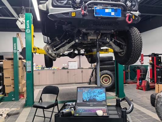
The required accuracy of the final model must be considered. A gear tooth profile that will be wire-EDM cut needs a different level of fidelity than a mounting bracket that will be laser-cut and welded. The AlphaScan’s metrology-grade accuracy, backed by INSVISION’s ISO 9001 and CNAS-accredited calibration processes, provides a reliable basis for reverse engineering tasks where the resulting part must fit existing assemblies.
The scanner’s ability to capture fine features such as small holes, thin ribs, and sharp edges is critical for parts that contain both organic and prismatic elements. The handheld form factor also means the scanner can be brought to the part, whether it is still mounted on a machine, sitting in a maintenance crib, or on a pallet in the receiving area.
This flexibility reduces the risk of damaging a fragile or worn part during transport, and it keeps the reverse engineering workflow grounded in the actual condition of the asset, not a cleaned and idealized version.
Hangzhou Insvision Technology Co.,Ltd.
Address: Building 1, No. 1399 Liangmu Road, Yuhang District, Hangzhou, Zhejiang 311121, China