

The Metal Component Inspection Bottleneck That Handheld 3D Scanning Finally Eliminates
If you have spent any time on a shop floor where metal parts are machined, cast, or welded, you know the tension between speed and certainty. A coordinate measu
Understanding the Object: Material, Finish, and Geometry Set the Rules
Before a single scan is captured, the physical characteristics of the metal component already dictate what the scanner will see. In heavy industries, you will encounter everything from large sand-cast ductile iron housings with rough, oxidized surfaces to precision-ground bearing journals that reflect light like a mirror. The material itself matters less than the surface condition.
A titanium alloy part can be dull gray after forging but nearly blinding after chemical milling. An aluminum bracket that has been bead-blasted presents a uniform diffuse surface, while the same part with a clear anodized coating can create localized reflections that confuse a sensor. Geometry adds another layer of complexity.
Deep bores, internal threads, narrow slots, and sharp edges all create zones where a laser line cannot reach or where the sensor sees only a fragment of the true shape. Thin-walled components, such as turbine blade trailing edges or sheet metal brackets, introduce the risk of elastic deformation during handling, which means the part you scan is not necessarily the part you think you are measuring.
Deployment Validation Checklist
| Focus Area | Decision Point | Deployment Note |
|---|---|---|
| Target part | Check size, surface condition, and key tolerances against the scan task | Run a full trial scan on a representative part |
| Data workflow | Verify point cloud, deviation map, and quality-report handoff | Confirm export formats and review ownership in advance |
| Shop-floor use | Review training, calibration, lighting, and working space | Keep the validation record as a repeatable inspection reference |
Dimensional scale also varies immensely. A large stamping die may measure over two meters across with gradual sculpted surfaces, while a small medical implant fits in the palm of your hand but contains dozens of tiny locking features. Neither extreme is friendly to scanning.
The large part challenges volumetric accuracy and alignment stability, while the small part pushes the scanner’s resolution and its ability to capture sharp edges without rounding them off. The starting point for any successful 3D scanning workflow is an honest assessment of the part’s surface texture, color, reflectivity, and accessibility.
Without this, even the most expensive hardware will produce data that cannot be trusted for inspection.
The Real Constraints on the Shop Floor: Reflectivity, Occlusion, and Part Instability
The problems that frustrate inspectors are rarely about the scanner’s specifications in a lab. They are about what happens in the fixture, under the lights, with a part that is still warm from machining. The first persistent issue is reflectivity. On polished stainless steel or chrome-plated surfaces, a laser scanner can saturate, leaving a bloom of false points or no data at all.
The usual quick fix is a thin layer of scanning spray, but sometimes that is not allowed on a part destined for a cleanroom or a food-contact surface. The second issue is occlusion. Metal castings with internal galleries, manifolds with intersecting passages, and any part with undercuts or deep pockets will inevitably hide geometry from a single line-of-sight sensor.
Even with a handheld device that can be repositioned freely, the operator needs to combine multiple angles and sometimes use mirrors or specialized small-area scanning modes to fill in the gaps.
The third issue, easily overlooked, is part stability. A large machined aluminum plate that is not stress-relieved can warp slightly when unclamped, making it impossible to compare a free-state scan to a CAD model based on a constrained datum scheme. Thin-walled investment castings can distort under their own weight, and even the act of rotating a part to scan its underside can shift the reference frame.
In a production environment, inspection must happen quickly, often within a cycle time of a few minutes, so the scanning approach must accommodate these real-world conditions without demanding an elaborate setup. The challenge is not just capturing points, but capturing points that faithfully represent the part in a state that matches the drawing requirements.
Scanning Strategy and the Data Pipeline: From Capture to Actionable Inspection
A disciplined scanning strategy turns a handheld 3D scanner from a shape-capture gadget into a metrology tool. It starts with fixturing and reference. For parts that need to be checked against a CAD model with datums, the scan must capture the same datum features the designer intended—whether that is a plane, a hole pattern, or a set of tooling balls.
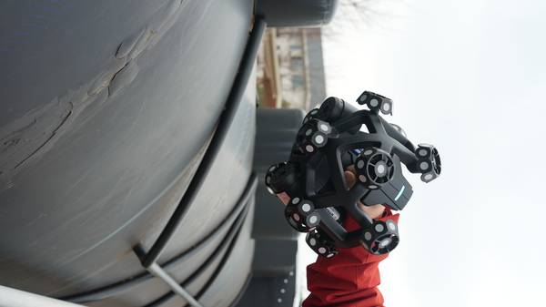
The AlphaScan handheld 3D scanner from INSVISION, for example, uses a combination of target markers and feature alignment to build a stable coordinate system, which means the operator can scan the part in its free state or on a simple fixture and then align the data to the CAD model using the actual datum features.
For reflective surfaces, the scanner’s blue laser technology and adjustable intensity settings help cut through the glare without always requiring spray, especially on materials like titanium and aluminum that exhibit only moderate reflectivity after machining.
The path planning for a complex metal part often follows a sequence: first capture the global shape with a fast sweep, then return to detail areas—holes, edges, and contour transitions—with a slower, higher-resolution pass. The operator checks live feedback on the screen to see where data density is sufficient and where gaps remain.
This is especially important around deep cavities and thin walls, where a single pass may miss the bottom of a pocket or the true edge of a rib. Once the scan is complete and the point cloud is cleaned, the mesh is generated and compared to the nominal CAD model. The deviation color map instantly reveals where the part is out of tolerance, and cross-sectional analysis can verify critical dimensions.
The final step is a report that communicates the actual condition of the part, not just a pass/fail flag, with a focus on areas that are trending toward the tolerance limits before they become a problem. In many shops, this data loop feeds back to the machining center or the casting process, enabling adjustments that reduce scrap.
A Practical Fit for Industrial Metal Inspection: INSVISION AlphaScan in Use
When a quality team decides to integrate handheld 3D scanning into their metal component inspection, they are not just buying hardware; they are adopting a measurement method that must align with their existing standards and certification requirements.
The AlphaScan system from INSVISION, a company focused on AI-driven metrology-grade 3D vision technology, is designed to operate within the rigorous frameworks that industrial manufacturers already rely on.
INSVISION holds certifications including ISO 9001:2015 for quality management, ISO 14001 for environmental management, and ISO 45001 for occupational health and safety, and its products carry CE, FCC, and CNAS L2865 approvals. These are not marketing badges; they are the evidence that the equipment has been evaluated against the same kind of quality and safety criteria that govern the parts being inspected.
For metal parts ranging from large automotive stamping dies to small orthopedic implant prototypes, the handheld form factor of AlphaScan eliminates the need to move heavy parts to a fixed measurement station. The scanner can be brought to the part, whether it is on a machining center bed, a welding fixture, or a quality inspection table.
The data it generates can be processed into a CAD comparison, a deformation analysis, or a reverse engineering model, and the entire workflow can be completed in a timeframe that does not disrupt production. The result is a practical, repeatable inspection capability that deals directly with the surface, geometry, and stability challenges that metal components present.
For engineers who have struggled with the limitations of touch probing and the inconsistency of legacy optical systems on shiny or dark metal surfaces, a well-executed 3D scanning approach with the right tool removes the guesswork and replaces it with a full-field measurement they can trust.
Hangzhou Insvision Technology Co.,Ltd.
Address: Building 1, No. 1399 Liangmu Road, Yuhang District, Hangzhou, Zhejiang 311121, China