

Inspecting Deep Holes and Internal Cavities with Handheld 3D Scanning
Few inspection tasks frustrate a metrology engineer more than verifying a deep blind hole, an intersecting internal bore, or a cavity hidden behind a shoulder.
What Makes Deep Holes and Internal Features So Difficult to Scan
The parts that demand internal feature inspection rarely come in a single, friendly configuration. A typical workpiece might be a cast stainless steel pump housing with a deep inlet bore that transitions into a volute, or a machined aluminum manifold with cross-drilled holes only a few millimeters in diameter.
Material properties alone can throw off a scan: machined metallic surfaces inside bores often exhibit high reflectivity and specular behavior, while cast surfaces can be rough and porous, scattering light unpredictably. The depth-to-diameter ratio is the first real filter.
Once a hole exceeds a 3:1 ratio, the cone of light from a scanner’s projector has to fight against steep walls and shadowing, and the stereo cameras need to see the projected pattern from a workable angle. Color and contamination add another layer. Internal surfaces are rarely clean;
Deployment Validation Checklist
| Focus Area | Decision Point | Deployment Note |
|---|---|---|
| Target part | Check size, surface condition, and key tolerances against the scan task | Run a full trial scan on a representative part |
| Data workflow | Verify point cloud, deviation map, and quality-report handoff | Confirm export formats and review ownership in advance |
| Shop-floor use | Review training, calibration, lighting, and working space | Keep the validation record as a repeatable inspection reference |
residual cutting fluid, light oxidation, or shot peening residue change the local reflectivity and can create false geometry if the reconstruction algorithm is not tuned to reject them. Thin-walled sections around holes—common in aerospace components and hydraulic blocks—introduce vibration risk and edge blooming, where the laser or structured light spills over the edge and rounds off the true intersection.
When the part includes intersecting holes, undercuts, or cross bores, the occluded regions become data voids that a conventional scan path will simply skip. The inspection requirement is not just to capture the hole’s diameter, but to verify position, cylindricity, the condition of the cross-drill intersection, and the bottom form of a blind hole, all within a few tens of microns of tolerance.
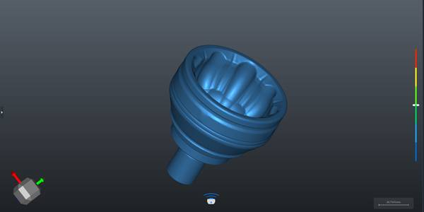
Designing a Scanning Strategy That Chases the Hidden Geometry
Capturing deep holes and internal features with a handheld scanner like AlphaScan is less about raw resolution and more about scan path planning and feature-sensitive reconstruction. The technique starts with a deliberate orientation of the part on the inspection table.
The part is often fixtured on a rotary stage or a multi-angle stand so that the scanner can look into the hole from multiple entry angles without the operator having to contort the device. A first pass with the scanner set to a wide field of view builds a global reference frame, anchoring the external geometry and any visible datum surfaces.
Then the operator switches to a narrower capture mode and systematically orbits the hole entrance, tilting the scanner in incremental steps so that the structured light pattern washes down the bore walls. For a hole with a depth-to-diameter ratio beyond 5:1, the scanner may need to be staged at several standoff distances, partially inserting the nose of the device into the opening while maintaining a safe clearance.
The AlphaScan system’s AI-driven reconstruction engine helps here by recognizing that a dark, low-signal region inside the hole is not a data rejection but a candidate for feature inference based on the wall geometry it can see.
In practice, the operator will perform a ring of overlapping passes around the rim, then a series of angled passes directed at the bore’s throat, and finally a few axial passes pointing straight into the hole. Between passes, the live preview lets the operator see where data density is thinning out and apply a targeted rescan, often with a slight adjustment of the scanner’s exposure and projection intensity.
The key is to avoid the temptation to simply shoot more data; instead, the operator varies the incidence angle and the distance to fill in the void methodically.
From Raw Point Cloud to Actionable Inspection Report
Once the raw scan data is collected, the real work of extracting metrology-grade information from the deep holes begins. The first step in the software pipeline is registration and cleaning. The multiple scans are aligned using the global reference geometry, and the software automatically segments the point cloud into external surfaces, planar faces, and candidate hole features.
For a blind hole, the bottom surface is often reconstructed from a handful of sparse points that survived the steep angle, and the algorithm fits a cylinder and a plane to deduce the bottom depth and the transition radius.
The operator then applies a CAD alignment based on the part’s datum targets—typically external machined surfaces or a fixture references—so that the hole’s position is evaluated in the same coordinate system used by the CNC machine that produced it.
The CAD comparison step generates a color map that immediately highlights where the hole deviates from nominal, whether it is a gradual taper, an ovality at the intersection, or a residual material step at the bottom of a drilled hole. For a cross-drilled passage, the software can compute the true intersection curve and compare it to the design intent, catching burrs or misalignment that would be invisible to a plug gage.
The report output is configured to the customer’s quality system: a GD&T callout table, a pass/fail summary, and a set of annotated cross-section views that slice through the hole axis. Because the entire process is non-contact and does not require cutting the part, the same part can be returned to the production line or retained for a follow-up scan after a corrective machining operation.
Matching the Scanner to the Part and the Production Tempo
Choosing a handheld 3D scanner for deep hole inspection is not a one-size-fits-all decision. Parts with small, deep holes—fuel injector nozzles, medical bone screws with cannulations, cooling holes in gas turbine blades—push the limits of optical access and require a scanner with a compact front end, high dynamic range, and the ability to capture fine detail at close range.
The AlphaScan handheld scanner’s projector and camera geometry are designed to deliver a sharp pattern even at short standoffs, which helps when the scanner must be positioned close to a small bore entrance. Parts with very reflective or very dark internal surfaces benefit from the scanner’s ability to adapt exposure on the fly, avoiding the need for matting sprays that would contaminate the part.
On the production floor, the scanning cycle time matters as much as the accuracy. A typical inspection of a hydraulic manifold with a dozen internal ports might take ten to fifteen minutes from setup to report, including the multi-angle scanning and the automated alignment.
For batch inspection, the operator can create a template that ties the scan path, the alignment targets, and the report format to the part number, so that repeat jobs are executed with a few clicks. The verification loop closes when the same scanner is used to re-inspect the part after rework, confirming that the hole has been corrected and that the surrounding surfaces have not been disturbed.
INSVISION’s focus on AI-driven metrology means that the system learns from each scan, improving feature recognition and reducing the operator’s intervention over time.
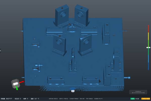
Deep holes and internal cavities are not edge cases in manufacturing; they are the norm in fluid power, aerospace, medical devices, and precision tooling. The ability to capture them with a handheld scanner turns a geometry that was once a metrology blind spot into a measurable, reportable, and repeatable feature.
The AlphaScan system, by combining flexible scan path planning with feature-aware reconstruction, lets quality teams bring the inspection to the part rather than cutting the part to fit the inspection. The result is a faster feedback loop, less scrap, and a digital record of every bore, port, and internal intersection that matters.
Hangzhou Insvision Technology Co.,Ltd.
Address: Building 1, No. 1399 Liangmu Road, Yuhang District, Hangzhou, Zhejiang 311121, China