

What It Actually Takes to 3D Scan Complex Mold Cavities
Mold cavities rarely cooperate. A deep draw die with undercuts, a multi-impression medical mold with mirror-polished cores, or a die-casting cavity coated in gr
The physical profile of a mold cavity creates
The physical profile of a mold cavity creates a set of recurring measurement obstacles. Surfaces range from EDM-finished matte to diamond-polished reflective, with draft angles that taper into deep ribs. Cavity depths can exceed 200 mm, and internal features like lifters, slides, and cooling-line bores introduce occlusions that frustrate single-line-of-sight instruments.
Thin walls between adjacent cavities, particularly in high-cavitation molds, flex under clamping pressure and shift the baseline geometry. Surface color often varies within the same cavity: a freshly maintained core sits bright, while a used cavity wall carries dark oxide staining or mold deposit. Traditional contact probing reads these surfaces point by point and misses the continuous form deviation between sampled positions.
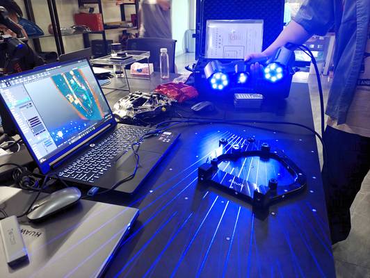
The AlphaScan handheld scanner, with its blue laser projection and multi-line scanning mode, captures full-field point clouds directly inside the cavity, reconstructing the complete negative shape without requiring the tool to be disassembled beyond standard opening.
Deployment Validation Checklist
| Focus Area | Decision Point | Deployment Note |
|---|---|---|
| Target part | Check size, surface condition, and key tolerances against the scan task | Run a full trial scan on a representative part |
| Data workflow | Verify point cloud, deviation map, and quality-report handoff | Confirm export formats and review ownership in advance |
| Shop-floor use | Review training, calibration, lighting, and working space | Keep the validation record as a repeatable inspection reference |
Common Questions
What should teams check when evaluating The physical profile of a mold cavity creates?
The physical profile of a mold cavity creates a set of recurring measurement obstacles.
What should teams check when evaluating A practical scan sequence for a cavity block?
A practical scan sequence for a cavity block starts with referencing the parting plane and tooling balls, followed by a controlled sweep of the cavity interior.
What should teams check when evaluating The downstream value of a dense cavity scan?
The downstream value of a dense cavity scan extends well beyond a pass/fail report.
A practical scan sequence for a cavity block
A practical scan sequence for a cavity block starts with referencing the parting plane and tooling balls, followed by a controlled sweep of the cavity interior. The scanner’s short standoff distance helps reach into narrow gate areas and vent grooves, while the software’s real-time mesh preview lets the operator confirm coverage before moving to the next impression.
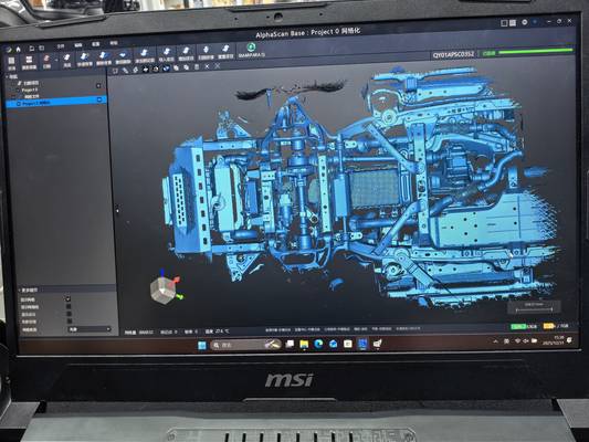
Where specular reflection causes dropout, the workflow adapts: a light dusting of scanning spray on localized mirror zones, combined with the scanner’s adjustable exposure, brings those surfaces back into the dataset without compromising the overall accuracy tolerance. The point cloud is then aligned to the CAD model, and a color map of deviations is generated within minutes.
That map isolates wear bands, sink marks, and dimensional drift from the original tool design. For a multi-cavity mold, the same scan routine repeats across all impressions, and the software overlays the deviation plots to check cavity-to-cavity consistency — a task that would take hours with a dial indicator and a surface plate.
The downstream value of a dense cavity scan
The downstream value of a dense cavity scan extends well beyond a pass/fail report. The point cloud data feeds directly into tool maintenance planning: if a specific rib shows progressive thinning over three inspection cycles, the trend is visible before parts go out of spec.
The same dataset can be used for reverse engineering a replacement insert, for simulating filling behavior with the as-measured geometry rather than the nominal CAD, and for correlating cavity variation with short-shot locations on the molding machine. In a repair scenario, the scan data guides the EDM operator by showing exactly where material needs to be removed and where the existing surface is already within tolerance.
INSVISION‘s software environment supports this closed loop, outputting inspection reports in formats that align with ISO 9001 documentation requirements while keeping the raw scan data accessible for engineering analysis.
The decision to bring handheld 3D scanning into
The decision to bring handheld 3D scanning into a mold shop depends less on the scanner’s headline specifications and more on whether the team can validate measurement performance against their own cavity geometries.
A recommended evaluation step is to scan a known cavity with a reference artifact — a calibrated gauge block or a tooling ball mounted in the mold base — and compare the scanner’s deviation map to an independent CMM measurement of the same features.
Parameters worth verifying include the scanner’s volumetric accuracy on deep narrow features, the repeatability of multi-scan alignment inside a single cavity, and the software’s ability to handle the polygon density required for tight-radius edges.
The AlphaScan handheld scanner is designed to operate in this accuracy-first workflow, with certifications including CE, FCC, and CNAS L2865 that provide a traceable baseline for mold shops that supply regulated industries.
Where a cavity’s geometry, surface condition, and inspection throughput demands push beyond the limits of manual metrology, a direct evaluation of the scanning system on the shop floor is the logical next step.
Hangzhou Insvision Technology Co.,Ltd.
Address: Building 1, No. 1399 Liangmu Road, Yuhang District, Hangzhou, Zhejiang 311121, China