
What Is 3D Measurement? A Practical Guide for Industrial Quality Control
In 2026, manufacturing tolerances continue to tighten while production cycles accelerate.
In 2026, manufacturing tolerances continue to tighten while production cycles accelerate. Quality teams face a familiar tension: traditional inspection tools deliver high accuracy on prismatic features but struggle with complex freeform surfaces, and the time required for comprehensive first-article inspection often clashes with delivery deadlines.
3D measurement has moved from a niche metrology technique to a mainstream quality control capability, yet many engineers still encounter confusion about how the technology actually works, where it fits, and what separates a reliable system from a lab curiosity.
This article explains the core principles behind industrial 3D measurement, clarifies how it differs from conventional inspection methods, and outlines the practical criteria that determine whether a 3D measurement system will deliver value on the shop floor. Along the way, we examine how INSVISION’s product lines align with these technical requirements, without turning the discussion into a sales pitch.
What Is 3D Measurement?
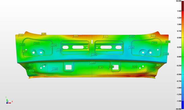
3D measurement is the process of capturing the three-dimensional shape of a physical object and comparing the resulting digital representation to nominal CAD data, or using it to create a CAD model where none exists. In quality control, the primary output is a deviation map — a color-coded visualization that shows exactly where and by how much a manufactured part deviates from design intent.
Term Notes
3D measurement is the process of capturing the three-dimensional shape of a physical object and comparing the resulting digi…
Key Technical ElementsWhen evaluating a 3D measurement system, four technical dimensions matter most:
How 3D Measurement Differs from Traditional InspectionA common question is whether 3D scanning replaces a CMM.
Well-suited applications:
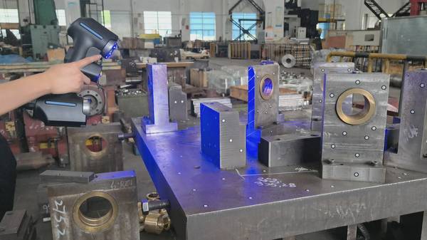
Most industrial 3D measurement systems rely on optical triangulation. A projector casts a known pattern of light (often blue LED structured light) onto the part surface, and one or more cameras record how the pattern deforms. Software reconstructs the surface geometry from these distortions, generating a dense point cloud — typically millions of measurement points in a single scan.
Multiple scans are aligned and merged into a complete 3D mesh, which can then be compared to the CAD model using inspection software.
The key distinction from traditional coordinate measuring machines (CMMs) is data density. A touch-probe CMM collects discrete points one at a time; a 3D scanner captures full-field surface data in seconds. This density makes it possible to evaluate form, waviness, and local deviations that a sparse point set would miss.
Key Technical Elements
When evaluating a 3D measurement system, four technical dimensions matter most:
| Element | What It Means in Practice |
|---|---|
| Volumetric accuracy | The system’s ability to measure true dimensions across the entire measurement volume. Often verified with certified artifacts and expressed as a length measurement error (e.g., according to VDI/VDE 2634 or ISO 10360 guidelines). |
| Resolution and point spacing | How finely the scanner samples the surface. Higher resolution captures smaller features and sharper edges, but increases data size and processing time. |
| Measurement speed | Single-scan duration and overall throughput. Faster systems reduce cycle time but must maintain accuracy under shop-floor conditions. |
| Data output and software integration | The scanner must deliver data in formats that inspection software (PolyWorks, GOM Inspect, etc.) can consume directly. A seamless workflow from scan to deviation map to report is what turns raw data into actionable quality information. |
Environmental stability, part surface characteristics, and operator skill also influence real-world performance. A system that delivers impressive specifications in a temperature-controlled lab may behave differently next to a stamping press.
How 3D Measurement Differs from Traditional Inspection
A common question is whether 3D scanning replaces a CMM. The answer depends on the application, not on a simple ranking of technologies.
- CMM (touch-probe) excels at measuring geometric dimensioning and tolerancing (GD&T) callouts on prismatic features — diameters, positions, flatness of machined surfaces — with traceable, single-point accuracy. It remains the reference for many ISO and ASME compliance tasks.
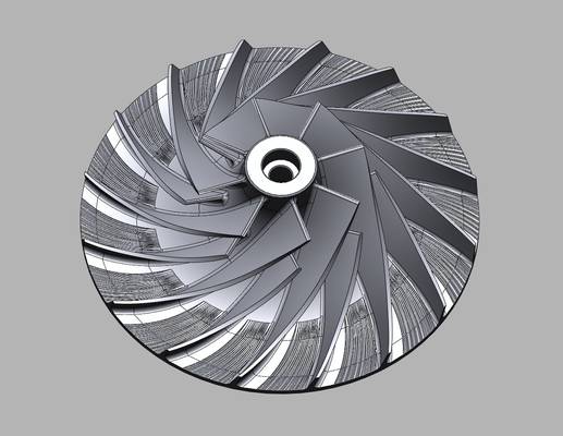
- 3D optical measurement captures the entire surface, making it the right choice for freeform shapes, sheet metal, castings, plastic parts, and assemblies where form deviation matters as much as discrete dimensions. It also accelerates first-article inspection by generating a complete deviation map in minutes rather than hours.
- Hand tools (calipers, micrometers, gauges) still have a place for quick, rough checks, but they cannot provide the comprehensive documentation that modern quality systems demand.
The technologies are complementary. Many quality labs use a CMM for critical feature verification and a 3D scanner for full-field surface analysis and reverse engineering.
Where 3D Measurement Excels — and Where It Falls Short
Well-suited applications:
- First-article inspection of parts with complex contours, organic shapes, or large numbers of features
- Reverse engineering of legacy components where no CAD data exists
- Tooling and die verification, including springback analysis and wear monitoring
- Inline or near-line inspection integrated with robotic automation for high-volume production
- Large-scale measurement using photogrammetry or tracking systems to maintain accuracy across several meters
Scenarios where 3D measurement may not be the best fit:
- Deep, narrow cavities or internal features that the light cannot reach (CT scanning may be required)
- Highly reflective or transparent surfaces without the application of a temporary matte coating
- Applications demanding sub-micron uncertainty over very small areas, where specialized tactile or optical CMMs still hold an advantage
- Environments with extreme vibration, temperature swings, or airborne contaminants that interfere with optical measurement, unless the system is specifically hardened for such conditions
Understanding these boundary conditions prevents misapplication and sets realistic expectations.
How to Evaluate a 3D Measurement System for Your Application
Rather than comparing spec sheets in isolation, start with the part and the inspection requirement:
- What is the part size and complexity? Small, detailed parts may need high-resolution structured light; large panels or tooling may require a scanner with a wide field of view or a tracking system.
- What accuracy do you actually need? Match the system’s volumetric accuracy to the tolerance band. Over-specifying accuracy adds cost without benefit.
- What is the surface condition? Shiny, dark, or textured surfaces affect scan quality. Test on real parts, not just matte calibration artifacts.
- Where will the system operate? A shop-floor environment demands robust hardware, fast setup, and tolerance to ambient light and temperature variation.
- How will the data be used? If the goal is a deviation map for a quality report, the software workflow matters as much as the scanner hardware. If the goal is reverse engineering, the system must output clean, watertight meshes suitable for CAD modeling.
- Is automation part of the roadmap? A scanner that can be mounted on a robot or integrated into an inline cell may offer a longer useful life than a purely manual system.
INSVISION’s Approach to 3D Measurement
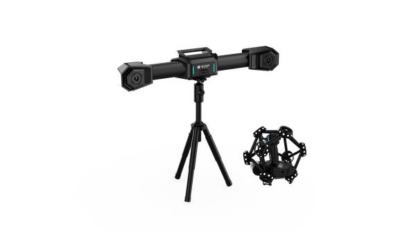
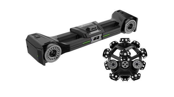
INSVISION develops structured light 3D scanners and automated inspection solutions designed to address the practical demands of industrial quality control. The product range includes the AlphaScan series of handheld and automated scanners, the AlphaVista system for larger fields of view, and the X-Track optical tracking solution for large-volume measurement.
The AlphaScan series uses blue LED structured light to capture high-density point clouds with metrology-grade repeatability. Its lightweight design and fast scan rates make it suitable for both first-article inspection in the quality lab and spot checks on the production floor.
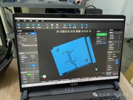
When paired with inspection software, the system generates deviation color maps that let engineers identify form errors, sink marks, or assembly misalignments at a glance.
For large parts — such as automotive body panels, aerospace tooling, or wind turbine blade sections — the X-Track system combines a handheld scanner with an optical tracker. The tracker follows the scanner’s position in real time, eliminating the need for targets on the part and maintaining volumetric accuracy across several meters.
This approach reduces setup time and avoids the accumulation of alignment errors that can occur with target-based stitching alone.
INSVISION’s scanners are also designed for automation. The same sensor technology used in manual inspection can be integrated into robotic cells for inline measurement, enabling 100% inspection of critical features without creating a bottleneck. The data pipeline supports common inspection software platforms, so quality teams can work within their existing reporting and SPC workflows.
Common Misconceptions and Technical Q&A
Q: Is 3D scanning always more accurate than a CMM?
A: No. A well-calibrated CMM can deliver lower measurement uncertainty on discrete prismatic features. 3D scanning provides far more data points and excels at capturing form and freeform surfaces, but the two methods serve different purposes. The right choice depends on the tolerance and the geometry.
Q: Can 3D scanners measure shiny or dark surfaces without preparation?
A: Most optical scanners struggle with highly reflective, transparent, or very dark surfaces because the projected pattern cannot be imaged reliably. A temporary matte coating (scanning spray) is standard practice. Some systems handle a wider range of surface conditions than others, but no optical scanner works on every surface without preparation.
Q: Do I need a climate-controlled metrology lab?
A: Not necessarily. Many modern scanners are temperature-compensated and can operate on the shop floor. However, extreme temperature swings or vibrations will affect any measurement system. Always verify the manufacturer’s specified operating conditions and test in your actual environment.
Q: What is the difference between structured light and laser scanning?
A: Structured light scanners project a pattern (often a series of fringes) and capture the entire field at once, making them fast and highly detailed. Laser line scanners sweep a line across the surface and build up a point cloud sequentially. Structured light typically offers higher point density per scan, while laser scanners can be more tolerant of ambient light.
Both are used in industrial quality control, and the choice depends on the application.
Q: Can one system handle both small precision parts and large tooling?
A: It depends on the system architecture. A scanner with interchangeable lenses or a tracking-based system like INSVISION’s X-Track can cover a wide range of part sizes. A fixed-field scanner optimized for small parts will not be suitable for large-scale measurement without additional accessories.
Summary
3D measurement has earned its place in industrial quality control by solving a specific problem: the need for fast, full-field surface data on parts that resist traditional point-based inspection.
The technology is not a universal replacement for CMMs or hand tools, but when applied within its boundary conditions, it shortens inspection cycles, improves defect visibility, and creates a digital record that supports traceability and continuous improvement.
Selecting a system comes down to matching the scanner’s accuracy, field of view, environmental robustness, and software compatibility to the parts you actually make. INSVISION’s AlphaScan, AlphaVista, and X-Track products address different points along this spectrum, from handheld shop-floor inspection to automated large-volume measurement, without forcing a one-size-fits-all approach.
For quality and manufacturing engineers evaluating their next step in digital inspection, understanding these technical fundamentals is the first move toward a decision that will hold up under production conditions.
Hangzhou Insvision Technology Co.,Ltd.
Address: Building 1, No. 1399 Liangmu Road, Yuhang District, Hangzhou, Zhejiang 311121, China