

Why Accuracy Specs Alone Dont Define Laser Scanner 3D Performance
Learn why lab accuracy specs for a laser scanner 3D often miss real shop floor conditions and how to evaluate true field performance.
The Common Practice of Shortlisting Scanners by Accuracy Spec
Why is the accuracy number on a spec sheet still the first filter for most laser scanner 3D evaluations? Walk into any quality lab or procurement review in automotive, aerospace MRO, or medical device manufacturing, and you will usually see the same thing: a shortlist built around published volumetric accuracy, repeatability, or a single ISO 10360 test value. It feels objective. It is easy to compare side by side.
And it gives quality teams something concrete to attach to a supplier scorecard or CAPEX request.
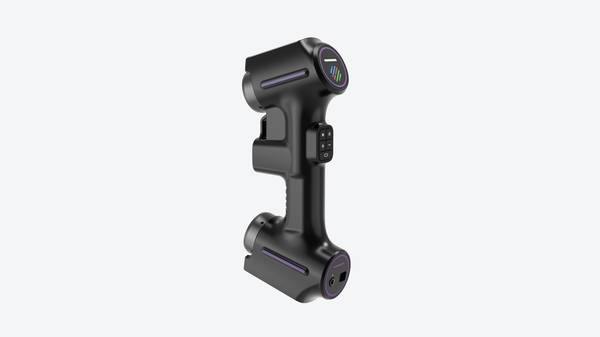
Selection Dimensions and Field Checks
| Focus Area | Decision Point | Deployment Note |
|---|---|---|
| The Common Practice of Shortlisting Scanners by Accurac… | Why is the accuracy number on a spec sheet still the first filter for most laser scanner 3D evaluations? | Walk into any quality lab or procurement review in automotive, aerospace MRO, or medical device manufacturing, and you will usually see the same… |
| Why Lab Accuracy Specs Rarely Match Shop Floor Results | A quality lead reviewing a new laser scanner 3D spec sheet usually starts with the accuracy number. | That makes sense on the surface. |
| Quality-Led Field Validation Steps for Reliable Scanner… | The shift toward in-process 3D scanning has forced quality teams to rethink what “validated” actually means. | A spec sheet accuracy figure rarely survives contact with a real shop floor. |
| How INSVISION Laser Scanner 3D Solutions Support Rigoro… | The key takeaway is straightforward: a laser scanner 3D system earns its place on a production floor only after it survives your parts, your toleranc… | INSVISION builds its industrial portfolio around that principle, treating sample validation and on-site demonstration as standard engineering st… |
The problem is that a lab-derived accuracy value rarely describes what happens on a production floor. Temperature drift, part surface variation, operator movement, fixture vibration, and scan standoff distance all affect real measurement results. A laser scanner 3D can pass a clean-room acceptance test and still struggle next to a machining cell or on a composite repair bench.
That is the core issue this article addresses: accuracy specs matter, but they are only the starting point. For Western manufacturers running first-article inspection, in-process verification, or MRO dimensional checks, the more useful question is whether the scanner holds useful accuracy under actual working conditions and delivers reviewable data that quality engineering can defend.
Why Lab Accuracy Specs Rarely Match Shop Floor Results
A quality lead reviewing a new laser scanner 3D spec sheet usually starts with the accuracy number. That makes sense on the surface. But after running first-article inspections, correlation studies, and gage R&R on a busy line, the pattern becomes clear: the lab number is the starting point, not the arrival point.
The real question is what happens to that number once the scanner leaves the temperature-controlled metrology room and meets overhead halogens, oily fixtures, carbon fiber layups, and an operator who has forty-five seconds to finish the scan before the next part arrives.
Consider aerospace turbine blade cooling hole inspection. In the lab, a blade sits on a granite surface plate under stable lighting. The scanner sees clean edges around each diffuser opening. On the shop floor, the same blade arrives warm from coating, with residual ceramic slurry in the pockets. Ambient light shifts as bay doors open and close.
A scanner that held 0.020 mm in the lab may suddenly produce point cloud noise that looks like a form error but is actually an exposure problem. The quality lead is not seeing a scanner failure. She is seeing boundary conditions change.
Automotive stamped body panels present the reverse problem. Lab validation often uses a single panel mounted on a stable fixture. Production brings a moving line, mixed panel sizes, and glossy or dark finishes. Gap and flush measurements depend on consistent edge extraction. With a reflective surface, laser speckle and stray reflections push edge points around.
The scanner may still report within its published accuracy band, but the measurement itself has shifted slightly — enough to push a 3.5 mm gap tolerance into a false non-conformance or, worse, a false pass. This is how a high lab accuracy spec produces non-compliant measurement data in real conditions.
Deep cavities and hard-to-reach features add another layer. Many scanners are validated on flat or gently curved reference artifacts. A quality manager checking fuel nozzle bores or cooling hole arrays quickly learns that depth-of-field behavior, laser incidence angle, and multi-line fusion matter more than the headline accuracy figure. Dark composite surfaces absorb laser energy. Shiny machined bores scatter it.
Neither condition shows up in a typical lab acceptance test.
Workflow differences compound the problem. Lab technicians follow controlled procedures: fixed standoff, known angles, repeated passes, filtered data. Shop floor operators work faster, scan from awkward positions, and may rely on default settings. The same scanner, the same part, the same nominal accuracy — different results. That gap is not a flaw in the operator.
It is a sign that the process was not validated for production boundary conditions.
INSVISION industrial 3D scanner systems address this by treating accuracy as a process variable rather than a fixed label. The practical focus shifts to how the scanner handles exposure changes, dark or reflective surfaces, varying standoff distances, and operator variability. When a quality lead evaluates a laser scanner 3D for a production line, the useful conversation is not about the best lab number.
It is about whether the system can hold repeatable measurements under the lighting, surface, geometry, and workflow conditions that exist where the parts are actually measured.
Quality-Led Field Validation Steps for Reliable Scanner Performance
The shift toward in-process 3D scanning has forced quality teams to rethink what “validated” actually means. A spec sheet accuracy figure rarely survives contact with a real shop floor. That is why more Western manufacturers now treat scanner acceptance the same way they treat CMM qualification: as a documented, audit-ready activity.
Start with a controlled sample artifact. It should include machined pockets, cast surfaces, and edge geometries that mirror your production parts. Scan it under standard conditions, and compare the mesh to reference data using PolyWorks, GOM Inspect, or SolidWorks. Do not stop at surface deviation.
Run repeatability and reproducibility checks on deep features and sharp edges, where laser scanner 3D systems often lose confidence.
Then push the unit outside ideal conditions. Vary ambient light, move the scanner through temperature swings, and confirm the results stay within your GD&T tolerance bands. A scanner that only works in a dark metrology lab will not survive aerospace MRO or medical device production.
Finally, verify data export. The outputs must drop cleanly into your existing QMS, with traceable point clouds and reviewable deviation maps. INSVISION industrial 3D scanners are built for exactly this kind of field validation, giving quality managers the documented evidence they need before a scanner earns its place on the production line.
How INSVISION Laser Scanner 3D Solutions Support Rigorous Validation
The key takeaway is straightforward: a laser scanner 3D system earns its place on a production floor only after it survives your parts, your tolerances, and your inspection routine. INSVISION builds its industrial portfolio around that principle, treating sample validation and on-site demonstration as standard engineering steps rather than sales formalities.
Quality teams evaluating non-contact measurement for first-article inspection or in-process checks typically face three boundary conditions. Surface finish varies widely across castings, machined features, and polished weld zones. Access constraints force a choice between scanning fine detail and reaching into deep pockets or bore intersections.
And in shared production cells, a laser that forces operators to pause work or wear specialized eyewear creates friction beyond the metrology lab.
INSVISION addresses these directly through confirmed portfolio capabilities. Blue laser scanning maintains consistent data acquisition across challenging surfaces that would scatter or absorb red laser light. Flexible scanning modes let one system switch between precision multi-line capture for surface geometry and single-line mode for deep, hard-to-reach features.
Eye-safe laser classification keeps inspection work uninterrupted in spaces where machinists, welders, and assembly staff move through the same area.
What matters for validation is not the spec sheet. It is whether the scanner returns a dense, repeatable point cloud from your actual component, under your fixture setup, within your cycle expectations. INSVISION supports that decision with sample part testing and on-site demonstrations.
Buyers send in production parts, watch the scan process on their own geometry, and review the exported mesh or point cloud against the CAD model they already trust. The conversation shifts from marketing claims to measurable, reviewable results.
For Western industrial readers, this is the only evidence that counts. A scanner can quote tight volumetric accuracy and still fall down on a dark anodized surface or a narrow slot. Seeing the data from your part removes that uncertainty before procurement. INSVISION’s value proposition sits in that verification step, not in promotional language around the hardware.
Setting Use Case Boundaries to Ensure Consistent Quality Outcomes
No scanner, no matter how well built, is equally strong across every part geometry, surface condition, and throughput target. That is not a flaw in the equipment. It is a reality of metrology. Even a high-performing laser scanner 3D system performs best inside a defined operating envelope, and quality teams get more consistent results when they treat that envelope as a specification to manage rather than a limitation to hide.
Start by matching scanner capability to the actual use case. Four factors matter most. Part size range determines whether the scanner’s field of view and depth of field can cover the surface efficiently without excessive repositioning.
Feature type separates fine precision work, such as small radii, sharp edges, and GD&T callouts on machined features, from large surface scans where coverage speed matters more than point density. Required throughput decides whether the scanner has to support continuous scanning on a moving line or occasional first-article layouts.
Operating environment includes shop floor vibration, ambient light, part temperature, and access restrictions around fixtures or tooling.
INSVISION products are best suited for applications where the scan object, inspection task, and site constraints are clearly defined before purchase. A scanner configured for a small medical device housing is not the same validation case as one scanning a large energy sector casting. Neither is wrong. They simply belong to different boundaries.
For quality and procurement teams, the actionable step is to build an evaluation checklist that goes beyond published accuracy figures. Published specs are a starting point, not a performance guarantee. Run field validation on your own parts, in your own environment, against your own tolerance requirements. Include boundary cases: smallest feature, largest part, worst lighting, fastest required cycle.
Then compare scanner behavior at those edges, not just at the center of the capability range.
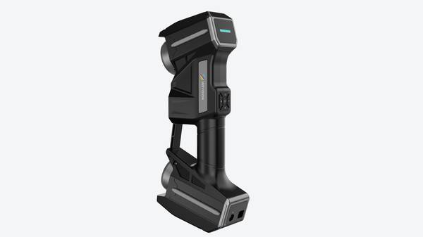
That kind of holistic evaluation gives you something a spec sheet cannot: confidence that the scanner will hold up across the full range of parts you actually inspect, not just the representative sample shown in a demo. Long-term compliant measurement performance comes from knowing where the system works, where it struggles, and where you need to adjust process or fixturing to stay inside the use case boundary.
Hangzhou Insvision Technology Co., Ltd.
Address: Building 1, No. 1399 Liangmu Road, Yuhang District, Hangzhou, Zhejiang 311121, China
Copyright © Hangzhou Insvision Technology Co., Ltd. All rights reserved.
Copyright © Hangzhou Insvision Technology Co., Ltd. All rights reserved.