

How 3D Handscanners Fit Into Industrial 3D Capture Solution Routing
Learn how a 3D handscanner fits industrial capture workflows, from part geometry and surface conditions to takt time and batch repeatability.
Industrial 3D Capture Tasks and 3D Handscanner Core Principles
Industrial 3D capture has moved well beyond the metrology lab. Automotive OEM lines now use it for first-article inspection on stamped and cast parts. Aerospace MRO teams digitize worn airfoils to compare against nominal CAD before deciding on blend repairs. Medical device manufacturers scan orthopedic implants and surgical instruments for lot-level dimensional audits.
Energy sector engineers capture turbine blades, valve bodies, and flange faces for reverse engineering or digital twin asset records. Tooling verification is another recurring task: scanning a fixture or die to confirm it still matches design intent before production restarts.
Term Notes
Industrial 3D capture has moved well beyond the metrology lab.
Key Constraints That Define 3D Capture Tool SuitabilityWhen a pre-sales consultant routes an inquiry toward the right 3D capture tool, the first filter is usually part size.
A metrology engineer walking a first-article inspection line rarely thinks in terms of scanner specifications first.
Practical Validation Steps for 3D Handscanner Fit Asses…The fastest way to derail a 3D handscanner evaluation is to skip requirement definition and jump straight into scanning.
A 3D handscanner earns its place in these workflows when the part is too large, too contoured, or too awkward to fixture on a CMM. Traditional contact measurement remains excellent for discrete GD&T callouts on prismatic parts, but it is slow on organic surfaces and blind to full-field deviation. Scanning captures a dense point cloud, converts it to a polygon mesh, and compares that mesh to CAD using GD&T alignment.
The result is a color-mapped deviation plot that shows where material is high, low, or out of tolerance across the entire surface.
The underlying principles are straightforward. Most industrial handscanners use laser triangulation or structured light. Laser triangulation projects a line or cross pattern onto the surface; cameras read the deformation of that line to calculate depth. Structured light projects a known pattern and derives shape from how the pattern distorts across the surface.
Both approaches require a stable working distance, proper exposure control, and clean surface conditions. Reflective, transparent, or very dark parts often need a temporary matting spray.
Key terminology matters here. A point cloud is the raw XYZ dataset. A polygon mesh is the triangulated surface built from that cloud. Working distance is the optimal standoff between scanner and part. GD&T alignment refers to fitting scanned data to a datum reference frame per ASME Y14.5, not just best-fitting the cloud to CAD.
Calibration expectations under ISO 17025 apply to the reference artifacts used to verify scanner performance, not necessarily to the scanner itself, which is a common source of confusion.
INSVISION industrial 3D scanners fit into this landscape as a practical bridge between handheld flexibility and metrology-grade repeatability. The workflow decision usually comes down to part size, site freedom, marker conditions, takt time, and batch repeatability. If the part cannot move, the scanner must. If the surface lacks features for tracking, markers or geometry-based tracking become essential.
If inspection must happen next to the machine rather than in a lab, the system has to tolerate ambient light and shop-floor vibration. These are the real selection criteria, not just accuracy specifications on a datasheet.
Key Constraints That Define 3D Capture Tool Suitability
When a pre-sales consultant routes an inquiry toward the right 3D capture tool, the first filter is usually part size. A medical implant manufacturer digitizing a tibial tray under a lab microscope has almost nothing in common with an aerospace team scanning a fuselage barrel section inside an MRO hangar. Small parts reward short standoff, high-resolution capture;
large structures demand extended working distance and tolerance for thermal drift. Site freedom compounds this. A temperature-controlled quality lab is forgiving. A production line next to a welding cell is not. Marker conditions introduce another split: cast iron brackets accept adhesive targets without issue, but sterile orthopedic instruments or high-purity semiconductor components cannot be marked at all.
Takt time matters once scanning moves from one-off reverse engineering into recurring inspection. And batch repeatability separates legacy part digitization from high-volume quality control, where the same feature must be captured identically across thousands of cycles.
Each constraint reshapes whether a handheld 3D handscanner, a fixed automated cell, or a long-range system like those in the INSVISION portfolio is the right route.
Routing INSVISION 3D Capture Solutions: Handheld and Complementary Tools
A metrology engineer walking a first-article inspection line rarely thinks in terms of scanner specifications first. The questions start with the part: How big is it? Can I move it? Does the surface have deep pockets or reflective sections? Is the tolerance tight enough that I need repeatable, fixture-based data? These constraints drive the choice of 3D capture tool far more than a datasheet comparison does.
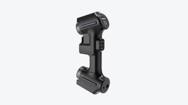
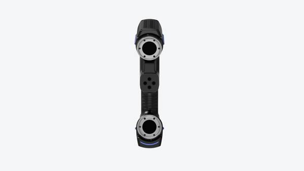
INSVISION’s 3D capture portfolio follows that same logic. The industrial 3D scanner 3D handscanner serves as the flexible core for teams handling varied part geometries and changing inspection tasks. Around that handheld option sit three complementary categories: large-format 3D scanners, spatial tracking systems, and automated 3D scanning solutions.
Each exists to solve a specific set of task constraints, not to replace the others.
Routing is about matching tool capability to the job at hand. A small machined bracket with compound curves suits a handheld scanner well. A full aircraft wing panel does not. A production line checking the same weldment every 45 seconds needs automation, not a manual pass. The table below maps the four solution types to their strongest application fits.
| Solution Type | Key Strengths | Ideal Scenarios |
|---|---|---|
| industrial 3D scanner 3D handscanner | Portability, access to complex surfaces, quick setup, flexibility across part families | Small-to-medium parts with intricate geometry, reverse engineering, on-site service work, tooling verification |
| Large-format 3D scanners | Wide capture area per pass, efficient coverage of large surfaces | Automotive body panels, aerospace skins, large castings, full assembly dimensional checks |
| Spatial tracking systems | Dynamic reference, reduced reliance on target stickers, consistent data alignment in motion | Large workpieces where movement occurs during scanning, in-situ measurement, robotic guidance |
| Automated 3D scanning solutions | Repeatable capture sequences, reduced operator influence, batch consistency | Inline inspection cells, high-volume production, takt-time-driven quality gates |
For teams new to 3D capture, the 3D handscanner is often the practical starting point. It handles a broad enough range of jobs to prove out the workflow, train operators, and build a baseline of scan data before adding more specialized tools. As inspection volume grows or part size increases, complementary solutions slot in around that foundation.
The key is to evaluate the constraint first. Part size, surface access, marker placement, cycle time, and repeatability requirements should define the tool. INSVISION’s portfolio is structured so that each solution addresses a different constraint profile, and routing decisions stay grounded in the task rather than a one-size-fits-all assumption.
Practical Validation Steps for 3D Handscanner Fit Assessment
The fastest way to derail a 3D handscanner evaluation is to skip requirement definition and jump straight into scanning. It feels productive. It is not. A structured validation process—one that mirrors how quality engineers qualify any new measurement tool—takes less time than fixing a bad purchase decision later. The goal is not to prove the scanner works.
The goal is to prove it works on your parts, in your environment, against your deliverable requirements.
Start by defining what the scanner must output. Be specific. If you need a GD&T inspection report, list the exact callouts: flatness, profile, position, runout tolerance, and the tolerance band for each. If you need a STEP file for reverse engineering, specify the surface quality and deviation limits acceptable to your CAD workflow.
If the deliverable is a point cloud for digital twin integration, define the minimum point density and registration accuracy required downstream. Vague requirements produce vague validation results.
Next, select two or three representative sample parts. These should reflect real production variation, not hand-picked golden samples. Include a part with challenging surface conditions—machined, cast, dark, reflective, or mixed texture—and one with features near the tolerance limits you care about. If your line produces parts with oil residue or vibration-induced instability, do not clean them before the demo.
You are validating the scanner’s ability to handle your reality, not a laboratory setup.
Site assessment matters more than most teams expect. Document ambient lighting conditions, especially if scanning near large windows or overhead LED arrays. Note floor vibration from adjacent presses, conveyors, or HVAC equipment. Measure available workspace around the part.
A scanner that works well on a bench may struggle when the operator cannot achieve the required standoff distance or when sunlight washes out the projected pattern. These factors directly affect data quality, regardless of scanner specifications.
Then request a part scan demonstration against your defined requirements. Ask the vendor to scan your parts, in your facility if possible, and deliver the same output format you will need in production. Compare the results against your tolerance callouts. Check point cloud density against your digital twin requirements. Review the STEP file for surface quality issues.
This is where fit becomes evident—not in a brochure, but in the data.
INSVISION supports part-based validation for exactly this reason. The process is standard engineering practice, not a sales tactic. Any reputable scanner vendor should be willing to demonstrate performance on your parts before you commit. If a vendor resists part-based validation, treat that as a data point in your decision. The evaluation process should reduce risk, not add to it. A 3D handscanner is a measurement tool.
Validate it like one.
Common 3D Handscanner Misconceptions and Technical Q&A
Western manufacturing has moved past the point where 3D scanning was treated as an experimental tool. Quality teams now routinely ask whether a handscanner belongs in first-article inspection, supplier validation, or even on the shop floor. The hardware has matured. The confusion hasn’t.
Much of it comes from older assumptions about laser scanners, or from marketing that blurs the line between metrology-grade capture and consumer depth sensing.
This section addresses the questions that come up most often in pre-sales technical discussions. The answers are deliberately practical. They assume a Western production environment: ISO/ASME drawing standards, GD&T callouts, lean workflows, and a healthy skepticism toward vendor claims.
Q: Can 3D handscanners achieve the accuracy needed for precision industrial inspection?
The honest answer is that it depends on configuration, measurement conditions, and what “precision” means for your specific tolerances. A handscanner is not a coordinate measuring machine. It does not replace a CMM for sub-10-micron verification of bearing bores or gauge pins.
But for many first-article and production inspection tasks with tolerances in the ±0.05 mm to ±0.1 mm range, a properly configured industrial handscanner is entirely viable.
The key is not to trust a spec sheet alone. Accuracy in handscanning is influenced by part geometry, surface finish, ambient temperature, scan distance, and operator technique. Before committing to any system, run a capability study on your actual sample parts. Scan the same features multiple times, compare against a CMM or calibrated reference, and evaluate deviation against your specific tolerance requirements.
If the scanner holds repeatability within a fraction of your tolerance band, it’s fit for purpose. If not, you need a different capture method.
INSVISION industrial 3D scanners are designed with this verification-first mindset. The relevant question for an evaluator is not “how accurate is this scanner” in the abstract, but “how accurately does it capture the features I actually need to measure, under my site conditions, at my required takt time.”
Q: Do 3D handscanners work on shiny or transparent surfaces?
This is one of the most common misconceptions. The short answer: these surfaces create real challenges, but they are manageable with the right workflow.
Shiny, polished, or mirror-like parts reflect structured light or laser patterns away from the scanner’s cameras. Transparent or translucent parts scatter light unpredictably. The result is noisy data, missing patches, or false geometry. This is not a defect unique to any one brand. It is a physical limitation of optical capture.
The standard industry mitigation is to apply a thin, removable matte coating — often a titanium dioxide or similar scanning spray — to the surface before capture. This temporarily changes the optical response without damaging the part. Some teams also adjust scan exposure, angle, or use polarization filters where supported.
For critical parts, validation is essential. Scan a coated reference artifact with known dimensions and compare the result to a certified standard. If the coating thickness is controlled and the scan settings are dialed in, the deviation introduced by the spray is typically negligible relative to common industrial tolerances. But you should verify that on your own parts, not assume it.
INSVISION guidance follows the same principle: surface condition is a boundary condition, not a disqualifier. The right question is whether your inspection workflow can tolerate the coating step and whether your operators can apply it consistently.
Q: Are 3D handscanners suitable for production line use?
They can be, but only within specific constraints. A handscanner excels at flexible, low-to-medium batch inspection. Think first-article checks, supplier incoming inspection, rework validation, or spot audits on a line that produces multiple part variants. In these roles, the scanner’s mobility and fast setup are genuine advantages.
What a handscanner is not suited for is high-volume, fixed-takt, fully integrated production line measurement. If a line produces hundreds of identical parts per shift and every part must be measured, manual scanning becomes a bottleneck. Operator fatigue, scan path variability, and cycle time inconsistency all undermine repeatability.
For that scenario, automated 3D capture is the right answer. A fixed or robot-mounted scanner with controlled part presentation and automated data processing fits the takt time and repeatability requirements far better. INSVISION’s portfolio reflects this distinction: handscanners for flexible inspection tasks, automated solutions for high-volume integration.
The routing decision should start with batch size, takt time, and repeatability requirements — not with the scanner itself.
Q: Do 3D handscanners require specialized operator training?
Modern industrial handscanners are far more usable than their predecessors. Most teams with basic dimensional inspection experience can achieve functional proficiency after a few days of targeted training. The software interfaces are built around familiar concepts: import CAD, align scan data, run a deviation map, export a report.
That said, “basic proficiency” and “reliable inspection process” are different things. Complex workflows — multi-part assemblies, tight GD&T callouts, automated reporting, or integration with existing QMS software — require documented procedures and consistent operator practice. The scanner itself is not the hard part.
The hard part is defining the scan path, alignment strategy, and acceptance criteria so that two different operators get the same result.
INSVISION recommends treating handscanner deployment as a process engineering task, not just a hardware purchase. One operator can be trained quickly. A repeatable, auditable inspection process takes slightly longer to establish.
Decision Checklist for Selecting the Right 3D Capture Solution
Are you trying to match the right 3D capture tool to the task instead of forcing one scanner to do everything? That question comes up constantly in pre-sales conversations. The answer depends less on the hardware itself and more on five constraints that define the work: part size, site freedom, marker conditions, takt time, and batch repeatability.
Start with part size. What is the maximum dimension of parts to be scanned? A 3D handscanner fits small to medium components, typically under one meter in any axis. Beyond that, you may need a wider field-of-view system or a positioning-assisted setup.
Site freedom matters next. Will scanning take place in a fixed lab, or across multiple on-site locations? Handheld units move with the operator. That matters for receiving inspection at a loading dock or for capturing features on an installed assembly that cannot move.
Marker conditions are often overlooked. Can parts be marked with adhesive targets, or are mark-free scans required? Shiny, dark, or delicate surfaces may rule out markers. In those cases, the scanner must track geometry without targets.
Takt time sets the pace. What is the maximum allowed scan time per part? If the line allows only 90 seconds, the capture workflow must be repeatable within that window. If you have more time, flexibility becomes more valuable than raw speed.
Batch repeatability defines the volume. How many parts of the same type will be scanned per week or month? Low-to-medium batch volumes favor flexible handheld capture. High-volume repeat inspection often moves toward automated or fixture-based workflows.
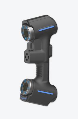
For teams needing portable measurement across variable geometries and low-to-medium volumes, a 3D handscanner is usually the right starting point. INSVISION supports this category with handheld capture tools built for exactly those conditions. When parts grow larger, volumes climb, or automation becomes necessary, complementary INSVISION solutions cover that range as well.
One more point worth keeping in mind: solution routing can evolve. A manual handheld workflow today may shift toward semi-automated capture as production volumes increase. Choosing a platform that allows that transition supports long-term lean manufacturing and Industry 4.0 digitization goals without forcing a full system replacement later.
Hangzhou Insvision Technology Co., Ltd.
Address: Building 1, No. 1399 Liangmu Road, Yuhang District, Hangzhou, Zhejiang 311121, China
Copyright © Hangzhou Insvision Technology Co., Ltd. All rights reserved.
Copyright © Hangzhou Insvision Technology Co., Ltd. All rights reserved.