
Industrial 3D Scanning Methods for High-Mix Metrology Workflows
Explore 3d scanning methods for high-mix inspection, blue laser handheld metrology, scan-to-CAD reporting, and digital thread integration in plants today.
Industrial Context and Application Scenario
Industrial metrology teams are under pressure to inspect more complex parts while production windows continue to shrink. Freeform surfaces, machined alloys, deep pockets, and frequent engineering changes are common in aerospace, automotive powertrain, energy, and heavy equipment manufacturing.
Traditional touch-probe CMM workflows remain valuable for high-accuracy point measurement, but they can become a bottleneck when every new part family needs a fixture, a probe program, and a controlled metrology-room queue. In this environment, 3d scanning methods give quality teams a practical way to capture full-field geometry closer to production and connect inspection data to the digital thread.
Typical Operating Conditions and Core Pain Points
A realistic use case is a high-mix machining cell producing structural brackets, housings, manifolds, and cast or forged components for regulated supply chains. Part geometry changes regularly, first-article inspection must follow documented quality requirements, and deviations need to be understood before a full batch moves downstream.
The issue is not only measurement accuracy. The larger challenge is how quickly useful dimensional data reaches the engineer who can act on it. A CMM may verify critical datums with excellent repeatability, but the queue time, fixture preparation, and inspection programming can delay feedback. Manual checks with height gauges, calipers, or feeler gauges may confirm a few dimensions but cannot describe the full surface profile.
Common pain points include:
| Production condition | Measurement challenge | Impact on the workflow |
|---|---|---|
| Reflective aluminum, steel, or nickel-alloy surfaces | Optical noise and unstable point capture | Extra surface preparation or repeated scans |
| Deep cavities, bores, ribs, and flanges | Shadow zones and incomplete coverage | Missed geometry in critical areas |
| Frequent changeovers | New fixtures and CMM programs | Longer setup and metrology queue time |
| Regulated quality systems | Need for traceable accuracy and reports | Measurement data must support audit requirements |
| Digital manufacturing programs | Data must feed PLM, MES, or quality systems | Isolated files slow corrective action |
For these conditions, industrial 3d scanning methods are most useful when they provide portable acquisition, full-field surface capture, scan-to-CAD comparison, and documented measurement traceability.
Solution Design Approach
The practical solution is not to replace every CMM process. A better approach is to match 3d scanning methods to the inspection task. Touch-probe CMMs remain appropriate for tight datum structures, bore positions, and features where contact measurement is specified by the control plan.
Handheld 3D scanning is well suited for freeform surfaces, casting variation, profile inspection, reverse engineering, tool wear assessment, and rapid deviation analysis.
Laser triangulation is a proven industrial approach. A laser line or pattern is projected onto the part surface, and the reflected geometry is converted into a dense point cloud. Blue laser scanning, commonly associated with shorter wavelengths such as 405 nm, is especially relevant for reflective machined surfaces because it can improve surface capture stability compared with many red-light scanning workflows.
INSVISION AlphaScan applies blue laser technology with AI-assisted reconstruction to support shop-floor metrology. INSVISION AlphaVista also uses blue laser scanning technology for industrial measurement tasks. In a high-mix environment, these 3d scanning methods help operators capture complex geometry without building a dedicated fixture for every part family.
Deployment Process from Part to Report
A repeatable workflow is essential if 3d scanning methods are expected to support production quality, not just occasional engineering checks.
1. Preparation
The operator places the part on a stable surface near the machining cell or inspection area. A dedicated rotary table or part-specific CMM fixture is usually not required. If the component includes hidden flanges, deep bores, or large smooth surfaces, adhesive reference targets can help maintain alignment during multiple scan passes.
The operator connects INSVISION AlphaScan to a ruggedized workstation running the INSVISION 3D software suite.
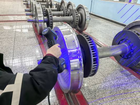
2. Scanning
The operator moves INSVISION AlphaScan around the component while watching the live point cloud. Blue laser projection supports scanning of reflective machined surfaces with less dependence on coating or developer spray. For complex geometries, the operator can approach the part from several angles to reduce shadow zones around ribs, pockets, and cavity features.
AI-assisted alignment helps stitch multiple passes into a coherent dataset. This is important in practical 3d scanning methods because operators need to know during acquisition whether the scan is complete, rather than discovering missing surfaces after the part has moved
Hangzhou Insvision Technology Co.,Ltd.
Address: Building 1, No. 1399 Liangmu Road, Yuhang District, Hangzhou, Zhejiang 311121, China