
High-Throughput 3D Scanning Instruments for Aerospace and Automotive First-Article Inspection
Accelerate first-article inspection in aerospace and automotive with high-throughput 3D scanning instruments. Discover how INSVISION streamlines FAI workflows and GD&T reporting.
Introduction: The Bottleneck in Large-Component Verification
In aerospace and automotive manufacturing, verifying the first article of a new component is a critical but time-consuming gate. Large parts like wing assemblies, fuselage panels, or vehicle chassis demand comprehensive dimensional validation against CAD models to ensure downstream assembly and performance. Traditional touch-probe CMMs, while accurate, create a significant bottleneck.
Key Points at a Glance
- In aerospace and automotive manufacturing, verifying the first article of a new component is a critical but time-consuming gate.
- Consider the standard first-article inspection (FAI) for a composite aircraft panel or a large automotive casting.
- The goal shifts from point measurement to comprehensive surface capture.
- For large-component FAI, the INSVISION AlphaScan is engineered to tackle the specific pain points of scale and workflow integration.
The process of programming, fixturing, and executing point-by-point measurements on a large surface can halt production for hours or even days. This delay directly impacts time-to-market and ties up expensive capital equipment. For these sectors, advanced 3D scanning instruments that provide full-field data with speed and traceable accuracy are a baseline requirement for lean, responsive manufacturing.
Typical Workflow and Core Pain Points
Consider the standard first-article inspection (FAI) for a composite aircraft panel or a large automotive casting. The workflow typically involves:
- Multiple Setups: The part must be repositioned multiple times to access all features with a CMM arm or stationary scanner.
- Manual Data Stitching: Individual scans from these setups require manual alignment and merging, introducing potential error and requiring expert operator intervention.
- Limited Data Density: Probing provides sparse data points, potentially missing local deviations, while slower scanning methods struggle with large areas.
- Reporting Lag: Generating the required ASME Y14.5-compliant Geometric Dimensioning and Tolerancing (GD&T) report and color deviation maps is often a separate, offline software task.
The result is a lengthy validation cycle where quality engineers wait for data instead of analyzing it.
Designing a Streamlined Scanning Strategy
The goal shifts from point measurement to comprehensive surface capture. The optimal strategy for large-part FAI requires 3D scanning instruments that minimize setup changes, automate data processing, and integrate reporting directly into the workflow.
This means selecting a 3D scanner with a field of view large enough to capture significant portions of the workpiece in a single frame, coupled with software capable of handling the resulting dense point cloud with industrial metrology protocols.
The Implementation Process: From Scan to Signed-Off Report
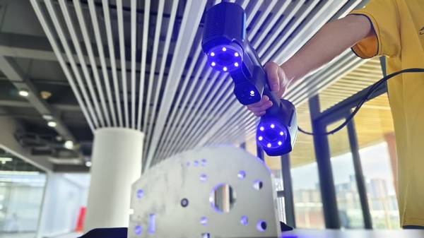
- Preparation: The component is placed on a stable surface or fixture. For reflective surfaces, a temporary matte spray may be applied. Targets are placed around the part to aid in automatic scan alignment if multiple angles are needed.
- Scanning: An operator uses the handheld scanner to capture the part’s geometry. With a large field of view, the entire surface of a medium-to-large panel can be captured in a handful of scan passes, often without repositioning the part itself.
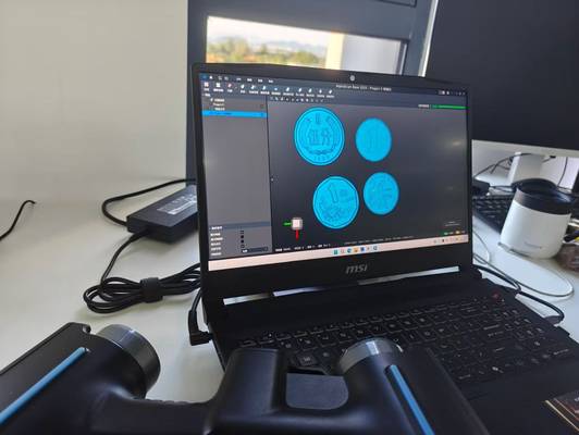
- Data Processing: The scan data is automatically aligned into a single, high-resolution 3D model. Proprietary algorithms filter noise and prepare the point cloud or mesh for analysis.
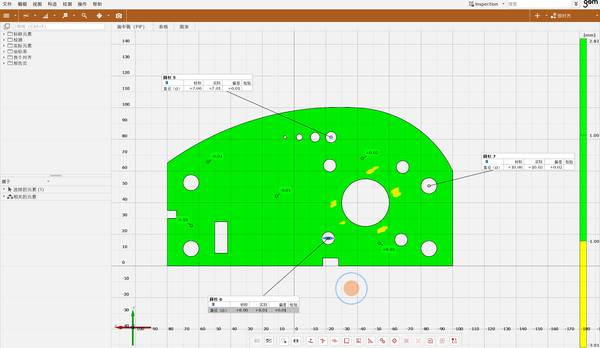
- Analysis & Reporting: The scan data is imported into the bundled metrology software. The CAD model is aligned to the scan data using best-fit or datum alignment methods. The software automatically calculates GD&T parameters and generates a full-color deviation map, visually highlighting areas out of tolerance.
- Delivery: The final report—including the deviation map, pass/fail status for each tolerance callout, and the aligned dataset—is exported for the quality record and shared with design and production teams.
How the INSVISION AlphaScan Addresses This Scenario
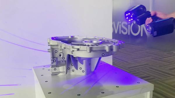
For large-component FAI, the INSVISION AlphaScan is engineered to tackle the specific pain points of scale and workflow integration. Its 650mm × 550mm scanning range allows engineers to capture expansive sections of a part in a single pass, directly addressing the bottleneck of multiple setups. This capability is particularly relevant for aerospace skin panels or automotive body-in-white components.
As one of the premier 3D scanning instruments for industrial metrology, the INSVISION AlphaScan features an integrated processing pipeline that reduces operator dependency. The bundled PTB-certified software moves the project directly from scan to analysis, with built-in tools for multi-source data alignment and automated GD&T reporting that meets ASME Y14.5 standards.
This closed-loop system ensures that the speed gained during scanning isn’t lost during post-processing.
Observable Outcomes in the Quality Lab
Adopting this approach transforms the FAI workflow. The most immediate effect is a significant reduction in the time required to go from part-on-stand to finalized report. Quality teams can complete inspections in a fraction of the time previously required by CMMs or smaller-field scanners.
The comprehensive color map provides intuitive, actionable insight that sparse point data cannot, enabling faster root-cause analysis for any non-conformances. Ultimately, this accelerates the release of new parts into production and frees metrology assets for other critical tasks.
Applicability to Related Industrial Scenarios
The principles of high-speed, large-area capture for comprehensive verification extend beyond aerospace and automotive FAI. These 3D scanning instruments are effectively applied in:
- Heavy Machinery & Energy: Scanning large weldments, turbine housings, or pump casings for deformation analysis and reverse engineering.
- Transportation & Rail: Inspecting composite body panels for buses, trains, or marine vessels.
- Pattern & Tooling: Digitizing large molds, dies, and patterns for wear assessment and digital archiving before production runs.
- Fabricated Structures: Verifying the dimensional accuracy of complex architectural or structural steel components.
Any scenario involving the inspection or digital documentation of medium-to-large, complex-shaped workpieces can benefit from this methodology.
Conclusion
The pressure to accelerate product development while ensuring stringent quality standards makes efficient first-article inspection a strategic imperative. Moving from traditional point-based methods to full-field 3D scanning instruments eliminates key bottlenecks in large-part validation.
Solutions like the INSVISION AlphaScan, designed with a large field of view and integrated metrology software, provide the throughput and traceability needed to keep pace with modern, data-driven manufacturing schedules. The result is a faster, more insightful quality gate that supports leaner operations and more confident production launches.
Hangzhou Insvision Technology Co.,Ltd.
Address: Building 1, No. 1399 Liangmu Road, Yuhang District, Hangzhou, Zhejiang 311121, China