

How Do You Match Ametek Creaform to Precision Inspection Workflows?
ametek creaform: Core Use Cases Driving Research into Ametek Creaform Metrology Solutions Core Use Cases Driving Research into Ametek Creaform Metrology.
Core Use Cases Driving Research into Ametek Creaform Metrology Solutions
Western manufacturing teams rarely start a metrology search with a scanner in mind. They start with a part that failed inspection, a supplier dispute over a dimensional report, or an MRO teardown that revealed unexpected wear. The search for Ametek Creaform and comparable portable 3D scanning systems almost always begins downstream from a specific engineering problem, not upstream from a specification sheet.
Key Points at a Glance
- Western manufacturing teams rarely start a metrology search with a scanner in mind.
- As Western manufacturing shifts toward automated inspection and digital twin workflows, metrology teams are being asked to qualify scanners agai…
- The shift toward portable optical metrology has changed how many Western manufacturers approach first-article inspection, tooling verification…
- The key takeaway is straightforward: your diagnostic parameter map should drive scanner selection, not the other way around.
Three use cases dominate the research phase. First, automotive tier 1 suppliers performing first article inspection on stamped brackets, cast housings, and welded assemblies need to verify dozens of GD&T callouts against ASME Y14.5 before production sign-off. CMM programming for a single complex bracket can take days.
Deployment Validation Checklist
| Focus Area | Decision Point | Deployment Note |
|---|---|---|
| Target part | Check size, surface condition, and key tolerances against the scan task | Run a full trial scan on a representative part |
| Data workflow | Verify point cloud, deviation map, and quality-report handoff | Confirm export formats and review ownership in advance |
| Shop-floor use | Review training, calibration, lighting, and working space | Keep the validation record as a repeatable inspection reference |
Portable scanning offers a faster path to a full surface deviation map, but only if the scanner can resolve tight profile tolerances on small radii and edge breaks.
Second, medical device manufacturers producing orthopedic implants and instrumentation face in-process dimensional verification requirements that cannot wait for batch sampling. A tibial tray machined on a five-axis mill needs immediate feedback on surface contour before it moves to polishing. The challenge is not just accuracy but repeatability across operators, shifts, and thermal conditions on the shop floor.
Third, aerospace MRO facilities assessing foreign object damage on turbine blades or corrosion on structural components need to quantify material loss without destructive sectioning. The part often cannot leave the hangar. The scanner must work in less-than-ideal lighting, on reflective surfaces, and produce data that can be compared against nominal CAD or a previously scanned reference state.
These tasks share a common thread. All three require dimensional data that holds up under audit. An ISO 17025 accredited lab cannot accept a color map screenshot as evidence. The underlying point cloud, alignment methodology, and deviation analysis must be traceable and repeatable. Lean manufacturing adds another constraint.
A scanner that takes forty minutes to set up may deliver excellent data but fail the takt time requirement on a line producing a part every ninety seconds.
This is where the selection process gets difficult. Generic spec sheet comparison obscures the real question. Accuracy stated in microns under lab conditions means little when the part is warm, the operator is wearing gloves, and the target surface is machined aluminum with residual cutting oil.
The core premise driving this article is straightforward: successful scanner selection depends on upfront application diagnostics rather than side-by-side parameter comparison. What is the part geometry? What are the tolerance limits? What is the reference data? What constitutes an acceptable deliverable? Answer those first, and the hardware decision narrows quickly.
Six Diagnostic Parameters to Map Before Evaluating Metrology Scanners
As Western manufacturing shifts toward automated inspection and digital twin workflows, metrology teams are being asked to qualify scanners against increasingly narrow task definitions. The shift is real: quality departments no longer buy a scanner for “general 3D capture” and hope it works across every job. They map the application first.
The difficulty is that scanner performance is not a single number. Accuracy specs, scan speed, and resolution interact with material, environment, and deliverable requirements. A system that handles a painted steel bracket in a lab may struggle with a reflective aluminum casting on a vibrating shop floor.
Skipping the diagnostic mapping step leads to misaligned purchases, rescans, and manual workarounds that erode the expected return.
The six parameters below are the same ones solution engineers use when specifying ametek creaform-class metrology equipment or evaluating INSVISION industrial 3D scanner options. They are not marketing filters. They are boundary conditions that decide whether a measurement workflow will hold up in production.
Object properties come first. Reflective aluminum castings, carbon fiber composites, and micro-featured medical implants each interact differently with structured light or laser projection. Surface finish changes the scanner’s ability to resolve fine features, while dark or translucent materials may require coating or adjusted exposure.
Geometry complexity matters too: deep pockets, thin walls, and sharp internal corners can produce data voids that tolerance analysis will not forgive.
Tolerance bands determine what “good enough” means. General assembly tolerances of ±0.5 mm are a different problem than micro-tolerance features at ±0.02 mm. Teams should separate global part geometry from critical GD&T callouts before selecting a scanner class. The tightest feature, not the average surface, drives the decision.
Facility environment is often underestimated. Shop floor vibration, temperature swings, and airborne oil mist affect both the scanner and the part. Cleanroom restrictions may prohibit certain coatings or require specific hardware form factors. A scanner qualified in a temperature-stable lab may drift during line-side use if ambient conditions shift across shifts.
Throughput targets define the takt time budget. Single-part batch inspection allows longer scan and post-processing cycles. High-volume line-side scanning demands faster capture, automated alignment, and repeatable operator workflows. The same part can be scanned with different equipment depending on whether the process allows two minutes or twenty seconds.
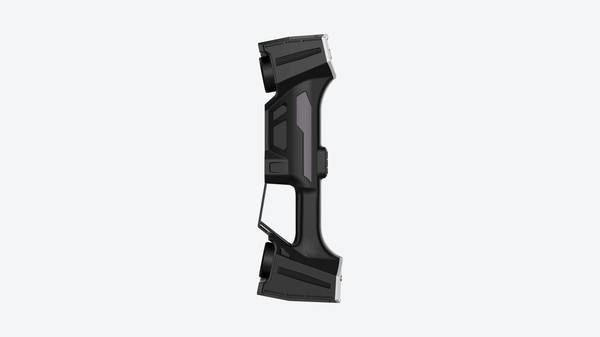
Access constraints include part size, hard-to-reach features, and whether scanning occurs in-situ or on a lab fixture. Large weldments, installed assemblies, and confined internal cavities require different standoff distances and scanner ergonomics than small bench-top components.
Required data deliverables shape the software workflow. GD&T reports, STL meshes for reverse engineering, or CAD comparison color maps each require different processing steps. Some scanners excel at raw mesh generation but add friction when producing ASME-compliant inspection reports.
What often happens is that a team shortlists hardware based on a datasheet accuracy number, then discovers during pilot testing that the shop floor vibration or a reflective surface invalidates the quoted performance. The scanner is not defective; the mapping step was skipped.
A practical way to run the diagnostic is to create a one-page matrix for each part family. List the six parameters in rows, then fill in the actual production values. Where uncertain, mark the parameter for validation before purchase. This exercise usually reveals that the scanner decision is not about finding the highest-resolution system, but about matching capture, alignment, rescan, and validation steps to the real task.
For Western factories working with ametek creaform-related inspection workflows or evaluating INSVISION industrial 3D scanner technology, that mapping step is where the engineering judgment happens. The hardware matters less than the boundary conditions around it.
Common Capture Risks That Undermine Metrology Scan Accuracy
The shift toward portable optical metrology has changed how many Western manufacturers approach first-article inspection, tooling verification, and MRO documentation. Shops that once relied on fixed CMMs or hand tools now run structured-light and laser-based scanners directly at the production cell.
That flexibility is real, but it brings a different failure mode into focus: the scan result is only as trustworthy as the capture conditions.
A solution engineer walking into an automotive supplier or aerospace repair shop rarely sees a bad scanner. What they see is a good scanner asked to work outside its boundary conditions. The same class of device that performs well on a matte, rigid casting can struggle on a polished turbine blade, a thin-walled stamping, or a vibration-prone fixture near a machining center. The problem is not the brand.
It is the mismatch between the task, the surface, the environment, and the data deliverable.
This section breaks down the capture risks that quietly degrade metrology scan accuracy, even with well-regarded systems such as Ametek Creaform-class tools. The goal is not to single out any vendor. It is to give engineers and quality managers a practical checklist for on-site validation before they commit to a workflow.
One common failure is reflective surface glare. Polished metals, clear-coated composites, and freshly machined aluminum can scatter or saturate the scanner’s light path. The result is data dropout, false surface noise, or the software filling holes with interpolation. Operators then compensate by coating parts with developer spray, which adds time and can change thin-wall geometry by a few microns.
That may be acceptable for a casting, but not for a bearing journal or a sealing surface.
A second risk is limited line-of-sight for internal features. Deep bores, undercuts, cooling channels, and intersecting holes are hard to capture from a single scanner position. The scanner sees what the optics can see. If a feature is hidden behind a flange or inside a narrow cavity, the scan will simply omit it or reconstruct it poorly.
Engineers should map the minimum feature access before selecting a scanner class, not after the first failed inspection report.
Alignment drift on high-vibration shop floors is another overlooked issue. Portable scanners rely on reference targets, photogrammetry frames, or feature-based alignment to stitch multiple scans into one coordinate system. If the part or the scanner moves slightly during capture, or if floor vibration transfers through the tripod, the alignment can shift.
That produces a cloud that looks complete but carries subtle geometric distortion. For GD&T callouts on true position or profile, that distortion can push a good part out of tolerance.
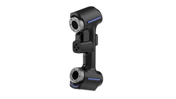
Resolution gaps for sub-millimeter features also matter. A scanner optimized for large surfaces may not resolve fine lettering, small radii, or narrow slots. The point spacing and depth resolution define what the system can actually measure. If the part has both large freeform surfaces and tiny functional details, a single scanner setup may not satisfy both requirements.
The right answer is often a different scan strategy, not a more expensive device.
Finally, throughput bottlenecks appear in large batch sizes. A scanner that excels on a single complex part may be too slow for 200 parts per shift. The time consumed by target placement, scan alignment, data cleanup, and report generation often exceeds the actual capture time.
Solution engineers should evaluate the complete measurement cycle, including operator handling and software workflow, rather than quoting scan speed alone.
The practical takeaway is that most scan failures stem from misaligned application fit, not poor tool quality. During on-site trials, validate reflective surfaces, hidden features, floor stability, resolution needs, and batch throughput. INSVISION industrial 3D scanners fit into this evaluation the same way: the task defines the tool, not the other way around.
Aligning Scanner Capabilities to Mapped Application Requirements
The key takeaway is straightforward: your diagnostic parameter map should drive scanner selection, not the other way around. Teams evaluating Ametek Creaform solutions often start with brand preference, then retrofit requirements to match. That sequence creates mismatches that surface later as poor scan data, excessive post-processing, or failed validation on the shop floor.
Think of the six diagnostic parameters as a fingerprint. High-detail small-part inspection with tight GD&T callouts typically pushes toward structured light systems, where dense point clouds and short standoff distances serve fine feature capture well. Reflective stampings, castings, or outdoor field work shift the balance toward laser-integrated architectures, which tolerate surface variation and ambient light better.
In-situ MRO damage assessment on large assemblies favors handheld form factors that let operators work around geometry rather than moving the part to a fixed scanner.
For teams whose mapped profile spans mixed-part workflows and variable shop floor conditions, INSVISION industrial 3D scanners offer a practical fit. The value is adaptability: handling both matte and semi-reflective surfaces, small brackets and larger weldments, without constant recalibration or environment control.
That matters when your parameter map shows no single dominant condition but instead a spread of requirements across shifts, materials, and inspection tasks.
No single tool covers every use case. Structured light struggles outdoors. Laser scanning may sacrifice fine-edge sharpness. Handheld ergonomics trade some repeatability for access. Final selection should always trace back to the team’s unique mapped diagnostic profile, not to a vendor’s specification sheet.
On-Site Validation Workflow and Portable Scanner Use Case Boundaries
When an inspection team evaluates a portable 3D scanner, the real question is not whether the hardware looks capable on a spec sheet. The question is whether the system can produce repeatable, deliverable-ready data under actual shop floor conditions. That requires a structured validation sequence, not a one-off demonstration scan.
The first step is baseline scanning against a calibrated reference part with known dimensions. This anchors the system’s volumetric accuracy to a traceable artifact rather than a vendor-supplied sample file. The second step is repeatability testing across multiple operators and shifts.
Temperature drift, lighting changes, and operator technique all influence scan consistency, so running the same part at different times reveals whether the system tolerates normal environmental variation.
Deliverable compatibility comes next. Confirm that exported mesh or point cloud data flows into the required CAD comparison and reporting software without manual rework. Finally, throughput testing against takt time targets determines whether scanning plus post-processing fits the production cadence.
Portable scanning systems, including Ametek Creaform-class devices, fit best where parts cannot move to a lab, where surfaces are complex or freeform, or where rapid dimensional mapping outweighs extreme sub-micron accuracy demands. Coordinate measuring machines remain the better choice for ultra-high-tolerance lab work on prismatic features with tight GD&T callouts.
For internal stakeholders, present validation results as a boundary map: what the scanner proves capable of, what it does not, and how inspection routing should change as a result. That framing earns more trust than a blanket recommendation.
Hangzhou Insvision Technology Co., Ltd.
Address: Building 1, No. 1399 Liangmu Road, Yuhang District, Hangzhou, Zhejiang 311121, China
Copyright © Hangzhou Insvision Technology Co., Ltd. All rights reserved.
Copyright © Hangzhou Insvision Technology Co., Ltd. All rights reserved.